


Yes I know, I have two other projects in the works. A wireless trailer harness and my QuadCOP needs completed. Both of those projects are long term. This project however should be quick! As in completed in a weekend.
Synopsis
As many who know me, know that I like to fly extreme radio control jets. These jets have a speed limit imposed on
them via the AMA at 200 MPH. I've never known how fast my jets go. A buddy of mine who has the same jet as me,
clocked his jet a 180 MPH. However I have 50% more power than he does! So its safe to say I probably break the
speed limit unintentionally.
Another concept is G forces felt by the aircraft during flight. Since no one is on board the aircraft, no body takes too much care about the G forces. It will be interesting to see the G forces and I will be using a Microstack Accelerometer to keep track of MAX G's during the flight.
Details
There are two types of speed with aircraft, ground speed and air speed. Ground speed of course is how fast the
aircraft is moving relative to the ground. The AMA sets its limits based on ground speed.
Airspeed is how fast the air is moving over the aircraft.
As an example of how these differ, consider the following:
If there is a 30 MPH wind and an aircraft was sitting on the ground not moving, the airspeed of is 30 MPH despite
the fact the aircraft is not moving.
This gets tricky in the air. If an aircraft has an airspeed of 200 MPH, but there is a 30MPH head wind, the ground
speed is only 170 MPH. If the wind is coming from the tail of the aircraft, the ground speed may be 230 MPH but the
airspeed may only show 200 MPH.
Lets take a look at some options available to do this, and the advantages or disadvantages of each.
Radar Gun
This is a small unit that times radar pulses to calculate how fast an object is moving towards the gun.
Pros
- No modifications aircraft
- Can be highly accurate.
- Not affected by airspeed.
Cons
- The person using it must be perpendicular to the aircraft. This means that it will be heading directly for them at a high rate of speed.
- A cheap gun is $100USD, which has highly variant results
- A good gun cost several hundred dollars.
Speed Sensor/Pitot Tube
http://www.hobbyking.com/hobbyking/store/__7838__Airspeed_Expander_V3.html
Pros
- Can be highly accurate for wind speed.
- This is how real aircraft measure speed.
Cons
- Requires cutting a hole in the jet for the Pitot tube
- Will still need an Arduino to get the data out
- Senses Airspeed, not ground speed. Will be affected by airspeed which can be as much as 30 MPH.
- Cannot be transferred to other aircraft easily.
Acoustic Doppler Effect
This is a method of recording the sound of the aircraft as it passes by. A software is then used to calculate the
speed of the aircraft based on the doppler shifts of the sound.
Pros
- Cheap
- No modifications to aircraft
- Can use a cell phone
Cons
- Highly variant results
- Requires very controlled conditions
- Requires constant throttle settings
- Requires a low and close pass
- Realistically this method should use precise sound equipment in a controlled environment.
GPS Unit
You put this into your aircraft and fly around. It will then tell you the top speed you have reached during the
flight. A good device like this will record all coordinates and let you play back what happened in real time.
http://www.horizonhobby.com/DYN4401?
KPID=DYN4401&CAWELAID=320011980000141493&CAGPSPN=pla&catargetid=320011980000166150&cadevice=c&gclid=CMTFuOq-
58cCFQYvaQodPIkGpg&kpid=DYN4401
Pros
- No modifications to aircraft
- Accurate
- Can be transferred easily between aircraft.
- Not Affected by airspeed.
Cons
- Adds some weight to the aircraft
- Must be secured
- Care must be taken not to block GPS signal
- Measures ground speed, does not take into account altitude changes.
- Expensive at $100+
Naturally I choose the GPS unit. However, as Makers we can all tell that this is something we can make ourselves.
The prefab unit is $100, lets see if we can do better.
The hardware
I have two options I am considering. Both use the Microstack GPS.
Option 1
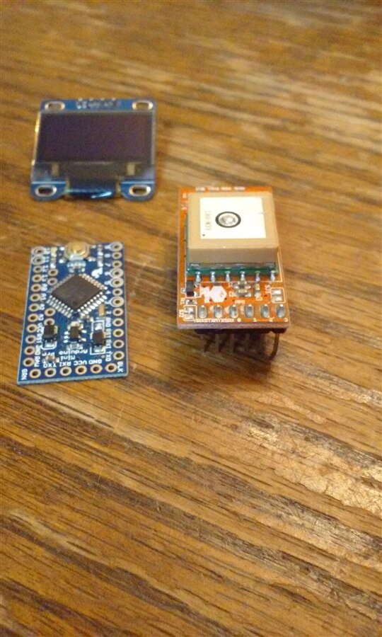
I plan to use an Arduino Pro Mini Clone. I have found a version that at $1.85USD it works perfectly.
I will also use an monochrome OLED. This is a 120X96 resolution.
I'll need a few tactile buttons.
I'll need a 3.3V and 5V regulator, and I chose the AMS1117 linear regulator in both voltages.
Option 2
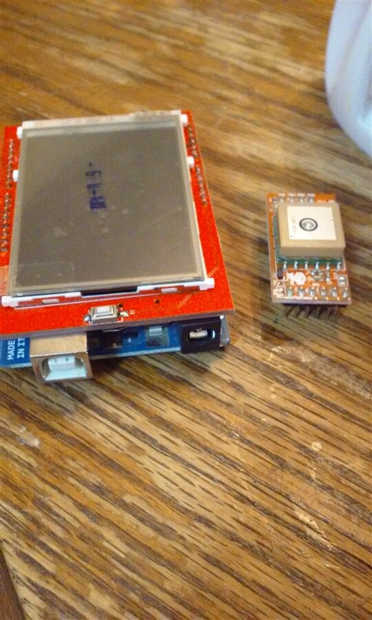
I have a clone TFT LCD clone that costs mea few $. It needs an Arduino UNO to function, as it is in the form of a
shield. This Screen also has a SD card which is nice for storing GPS data.
I wont need any buttons as it is a touch screen. I will still need a 3.3V regulator for the GPS unless I decide to
use the one onboard the UNO.
Comparison
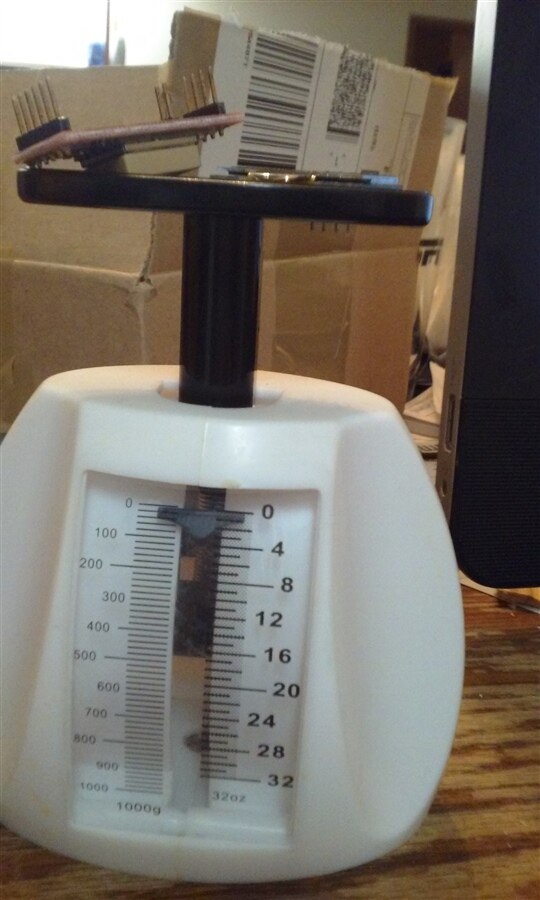
Option 1
Weight is < 1/2 oz.
Total cost (rounded):
| Part | Cost (USD) |
|---|---|
| Arduino Mini (5V) | $2 |
| GPS | $25 |
| OLED | $4 |
| AMS1117 (3.3V) | $.10 |
| AMS1117 (5V) | $.10 |
| MISC | $5 |
| Total | $37-$40 |
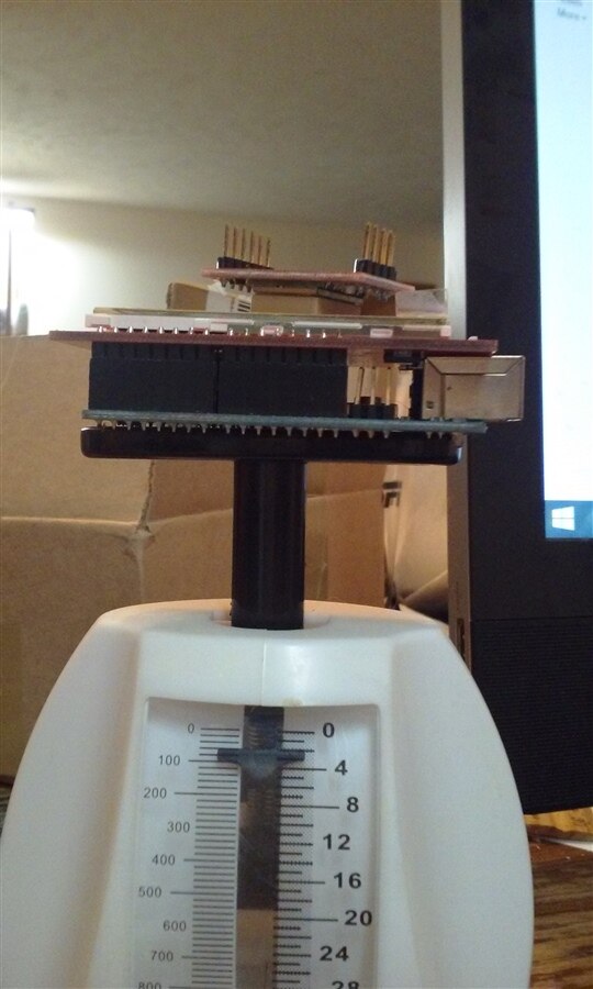
Option 2
Weight is about 2 oz
| Part | Cost (USD) |
|---|---|
| Arduino UNO | $10 |
| GPS | $25 |
| TFT LCD | $5 |
| AMS1117 (3.3V) | $.10 |
| AMS1117 (5V) | $.10 |
| Misc | $5 |
| Total | $45-$48 |
The MISC budget is just for items like buttons, connectors etc. For a case I will just be using blue core foam.
Either option is good, and the price is right which makes it a good project instead of buying a prefab unit.
Considerations
One thing that needs to be accounted for is altitude. If an rc aircraft is in a straight dive, the GPS will not
detect any changes in the coordinates and therefore the ground speed would appear to be 0. So any coding that is
done needs to take into climb and dive rates. The real issue is that most speed runs are going to be going
downhill or at an angle towards the ground. So the altitude vector (z) must be accounted for in the final speed
calculations.
To parse the NMEA sentences coming out of the GPS, it is a trivial task to use the TinyGPS++ library. This
library uses the Serial Port to read the GPS. This is perfect since the Microstack GPS unit uses the serial port
as well to send data. I feel that a frequency of 2HZ will be suffice for logging speed. The 16MHZ Arduino should
be able to handle this incoming data at 57600 bps. Any faster and I fear it may bog the Arduino down.
I do not plan at this time to log any GPS coordinates but simply keep track of the last highest speed and altitude.
I will use the EEPROM memory to store last values for viewing after a power cycle.
The user interface via the TFT or the tactile buttons is simple. I need the ability to reset the values for a new speed
run. I may add an option to turn the screen off and on as well, no need to have it update while in the aircraft.
A couple of status LEDs will also be used to indicate what is happening so I can see that it is working even with
the screen off. The Microstack GPS also has an LED to indicate everytime it does a fix.
For a case, I am going to just use 1/2" thick foam. I will cut rectangle out and embed the components directly
into the foam. This case will also act as a cushion in case the GPS unit is dropped or ever falls off the aircraft
(which happens!). You cant get much cheaper than that!
For the LCD, you know me, I bought a Chinese knockoff from Ebay. I got 2 of them. I used the Adafruit drivers and
of course they didn't work. I managed to get the demo working by hardcoding the device ID, for some reason it
cannot detect it. For the Touchscreen, it doesn't get the coordinates right so some fixing there will be required.
The 2nd screen I have the touchscreen doesnt even work!
The question is which option is better? Option 1 is lighter so it can be used for smaller aircraft, though I am
not sure I would have a desire to measure speed. Option 2 just seems more modern with the cell phones and tablets
we have these days. It certainly would be more snazzy.
I am going to do some testing with the LCD I bought, and see if it is going to be easy to get working. If not I want to go the other route the OLED and tactile buttons.
Calculating Velocity
I could use some input here but my thoughts are pretty simple. The GPS give the coordinates and I have a function called "DistanceBetween" that gives the arc length between two GPS points. This function ignores altitude and assumes you are on the surface of the earth. The speed is just the distance travelled over the time lapsed. The unit will display the moving average of the speed over the last 3 measurements. This will help smooth out the jumps from the lack of resolution of the GPS for the small distances an RC aircraft travels.
A similar calculation is done for altitude. The change in altitude divided by the times lapsed gives the climb or dive rate. The absolute value of this is then just added to the ground speed.
If we have a calculated ground speed of 100 MPH and we happen to also climb 20 feet in the last second (13.64 MPH) then our total speed is 113.61 MPH. Does that seem correct?
I plan to start this project in full force next week and have it working in a few days there after.
Top Comments