


When I used to repair dental chairs it was very common to find a logic circuit communicating with a line voltage triac through an opto-coupler. The chair's actuators were typically 115 Volt AC motors. These opto couplers had an internal LED tied to a light sensitive semiconductor junction that would, when illuminated, fire the triac and allow AC line power to flow to the motor. Until a couple days ago, however, I didn't realize that opto couplers existed that would allow AC line voltage as an input and output would be information to a logic circuit.
I was working on a circuit board for a Midmark Sterilizer when I came across the LTV 814 Opto Coupler.

This Opto coupler has two opposite polarity LEDs on the input and a photo transistor on the output.
The sterilizer has a door switch that is in a 115 volt AC circuit as well as an over temperature cut out switch that is also part of a 115 volt AC circuit. The open or closed status of both of these switches needed to be monitored by the sterilizer's logic circuits. In this case the designer's choice had been to use the LTV814 AC opto coupler to convey the status of these switches to the logic circuits.
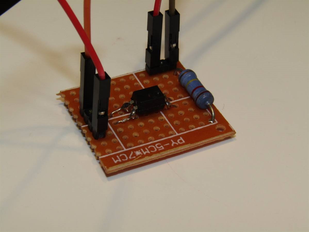
I salvaged one of the opto couplers from a scrap board and decided to experiment with it a little bit. The LEDs on the input have a voltage drop across their junctions of about 2 volts. The sterilizer board was using a 120 K Ohm 1 Watt resistor in series with the input to limit the current to the LEDs. 115 volts RMS divided by 120 K Ohms leaves us with slightly less than one milliamp of current. I had to adapt the SMD LTV 814 to through the hole for my experiment and I mounted it on a small piece of proto board. Of course the AC current would vary with time and the 1 mA was just the effective average current.
Here is the experimental board:
In order to see the effect of the whether there was AC on the input of the opto coupler or not I put together this circuit:
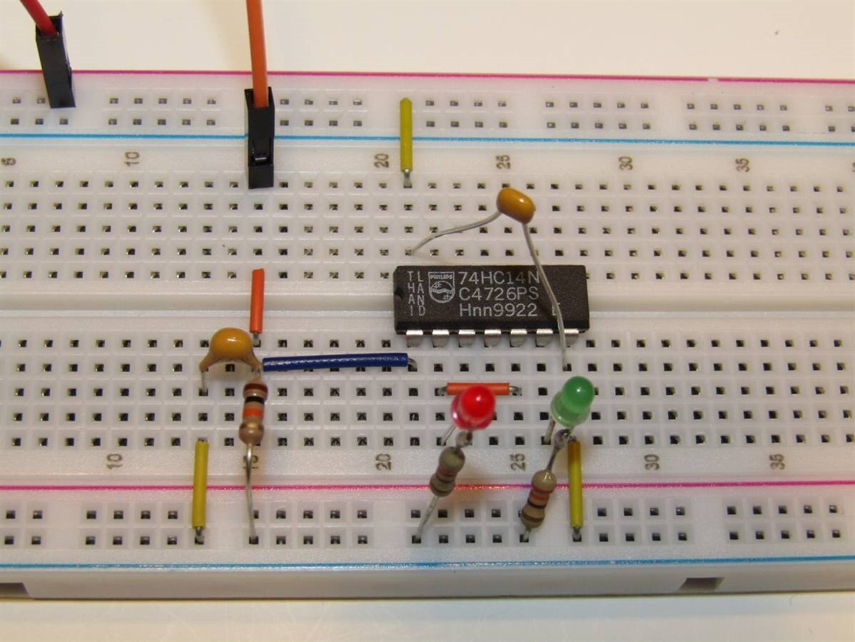
I put the photo transistor of the opto coupler in series with a 10 K resistor and connected the common point to the input of a 74HC14 Hex Schmitt Trigger IC. The Red LED is on the output of this first Schmitt Trigger. I also connected the output of this first section to the input of a second Schmitt trigger. The Green LED is on the output of the second Schmitt trigger. Since the Schmitt triggers invert we should see that the Red LED is lit when the AC power is off and the Green LED should light when the AC power is applied to the Opto Coupler. The capacitor across the 7414 is a decoupling capacitor and the other capacitor is a 10 uF ceramic that is being used to take the 120 Hz pulse out of the input to the Schmitt trigger. Since our input to the optocoupler is AC, 120 times each second the voltage on the LEDs is zero volts and this turns off the Schmitt trigger. The 10 uF capacitor stores the voltage during these off times and keeps the Schmitt trigger active. Once the power is turned off the voltage on the capacitor quickly drops due to the circuit through the 10K resistor and the Schmitt trigger goes low on the input.
I made a short video of the experiment in action:
This was not a very complicated experiment but it will be useful to me to know that I can use the LTV 814s, which incidentally cost about 11 cents from Farnell, to safely monitor the status of line voltage circuits. If you have applications in your builds where you need to know the status of a switch or voltage in a line voltage circuit perhaps it can be of use to you too.
John
Top Comments