


Before I begin to show you how I put together the control unit for the Automatic Home Water Shut Off System here are links to the first three chapters of this series:
Chapter one laid out some of the parameters for the power supply and control circuitry for the Automatic Water Shut Off. The system voltage was established at roughly 12 volts by virtue of the (2) 6 volt lead acid gel-cells that would be used for battery back up. The power supply of the control will be required to potentially recharge these batteries from a ground state to full charge as well as supply a sustaining trickle charge over long periods of time. The power supply also needs to be able to supply power to the sensor circuits, display circuits, and the trigger circuits that will fire the solenoid that releases the weight that closes the water valve.
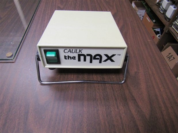
I began by looking through my grave yard for a suitable sized enclosure and a suitably sized power supply. The unit that seemed most appropriate began life as a Dental Cure light. If you want more information on what exactly a Dental Cure Light is here is a link to a previous blog where I gave some background: ( You can skip back here after the brief preliminary explanation of what a cure light is.)
Here is what the original control looks like without the power cord and light attachment:
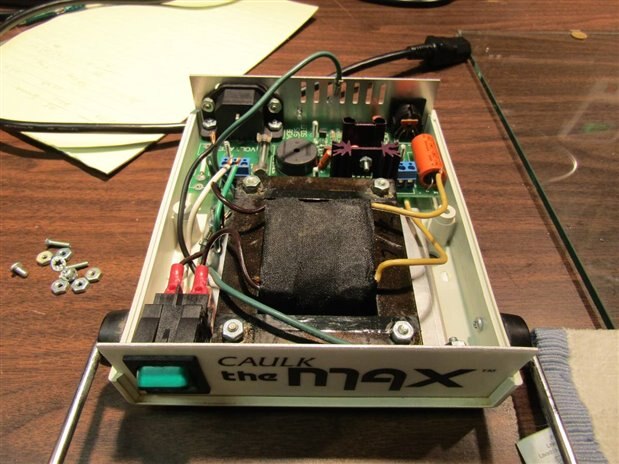
Internally there is a reasonably sized transformer capable of 17 volts at 3.5 Amps. The rest of the circuit board is devoted to a crude power supply and other components needed to make the cure light function. Here is a peak inside the unit before we begin the modification.:
Now that I had a prospective candidate for housing the control for the Automatic Shut Off System Control I began to breadboard and design the power supply and the rest of the control circuitry. The first project was the power supply. I decided to use a design the was introduced on the Forum a year or so ago by one of our Experts, Robert Peter Oakes . The design uses a full wave bridge from the transformer secondary to provide input to a MOSFET that is controlled by an OPAMP. I wanted to be able to accurately adjust and trim the final output so that I could bring the final trickle current to the gel cells to a very low level. The transformer of the cure light as well as the primary support circuitry was left in place. Tests revealed that the 17 VAC of the secondary when rectified and filtered produced an unregulated 22 volts. This provided plenty of room for the MOSFET and OpAmp to work.
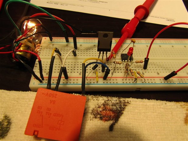
I simultaneously was bread boarding and developing a control circuit that would look at the sensors that were discussed in Chapter 2 and trip an alarm and the solenoid to close the water valve. Here is a picture of the bread board circuit under development:
The work on the power supply and the control circuitry eventually led to this circuit. Here is a schematic of the final prototype design. For simplicity I have left the mains switch, fuse, suppressors and other transformer primary circuit components off the schematic.

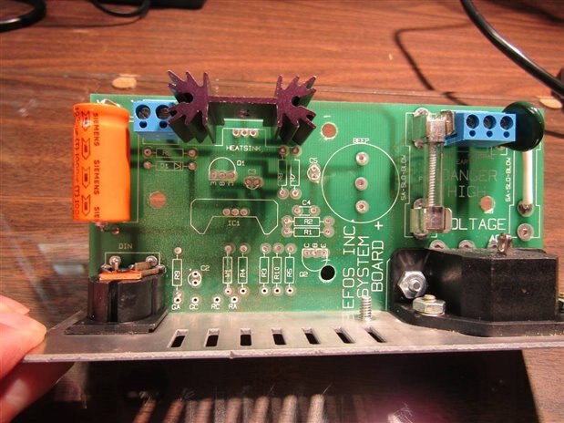
Now the fun part begins. You have probably been asking yourself by now; Didn't he say something about Frankenstein in the title of the blog? Yes I did. For this project I decided to fore go the usual construction of the control circuitry on a piece of clean prototype board. Just like the famous Dr. Frankenstein I have decided to remove all the parts of this Cure Light Control that do not suit me and put in on the same circuit board, using the same pads and traces, the parts that I need to make an Automatic Water Shut Off. Here is a picture of the circuit board as it looked originally and after the old components were removed.
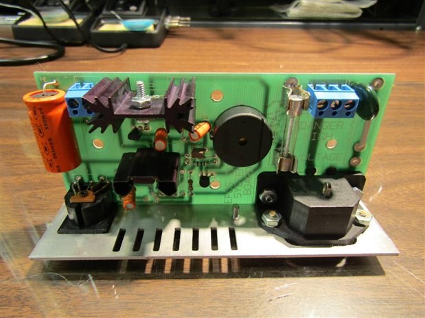
We might as well throw in a picture of the reverse side of the board too as this is where most of the new work will be done.
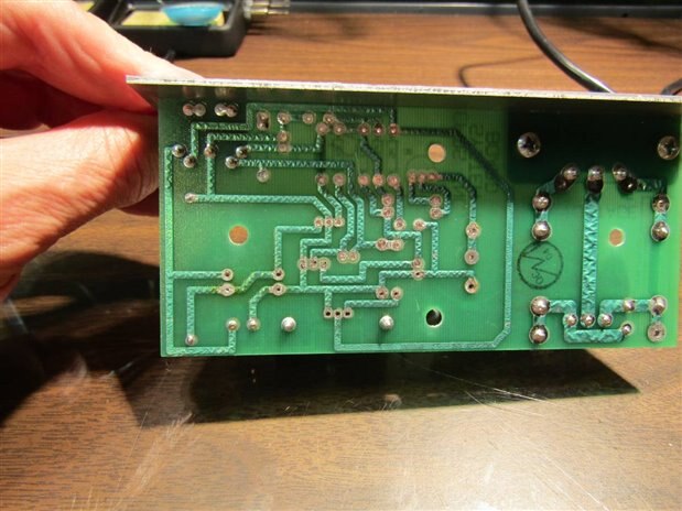
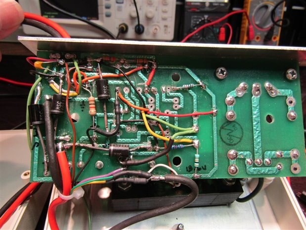
What I am doing with this board, I will call it Frankensteining, is only possible for me because I am working with very simple circuits like the one in the schematic above. The procedure involves a careful study of the layout of the existing traces and a careful, planned positioning of the new parts. Frequently it is necessary to cut traces and occasionally it is necessary to jumper traces. Pads for connecting components can be made with sections of the original traces. You will see unconventional structures like OpAmp Pillars and Comparator Pillars in this build. They are the results of necessity and convenience. This circuitry will work as it is all low frequency or linear in nature. This type of build would quickly fail if we were dealing with higher frequencies. Inductive and Capacitive coupling would interfere and our build would never rise from his slab. Skipping ahead here are a couple pictures of the completed transformation:

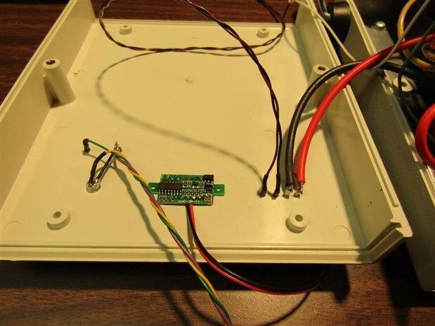
The controls, some of the terminal I/O, and the system volt meter were mounted to the original cover.
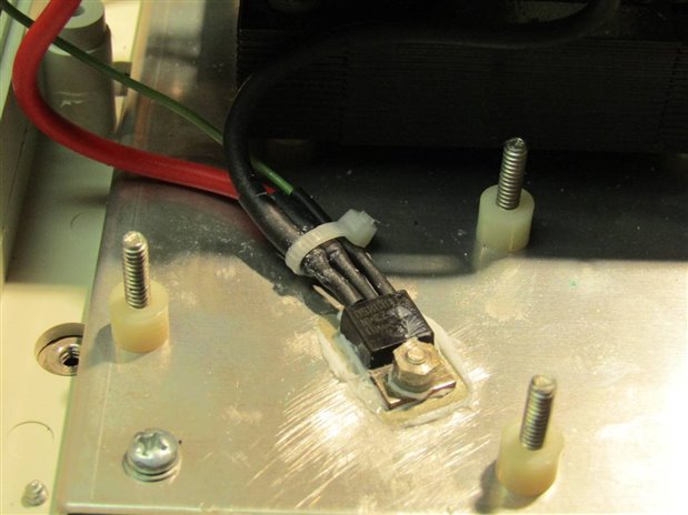
The power supply MOSFET was attached to an Aluminum base plate in the unit and the relay trigger MOSFET was mounted on a heat sink left from the original cure light circuit.
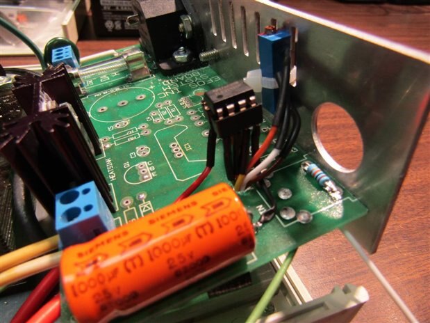
The trigger MOSFET is mounted on the black heat sink on the left side of the picture. This is a picture of the board before the rest of the sensor/trigger circuitry was installed but it gives the best picture of the OPAMP pillar that I referenced before. The blue ten turn trimmer is the voltage control for the unit.
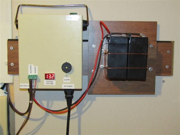
This is a picture of the completed unit mounted with its battery pack on the wall alongside the mechanical mechanism that closes the water valve.
In case you are interested it wasn't a totally smooth build. Those of you who have made things like this yourselves would not have believed me even if I told you it was smooth. I am sorry to report that (2) LM393 ICs gave their lives before I properly conditioned their power source and protected them from spikes. At the time of failures it is always very frustrating but in the end I always learn more when I have troubles. When I ran a test involving recharging the battery from full discharge I also ran into a concern with the heat that was being sunk by the power supply MOSFET. This problem was addressed by adding a half ohm current limiting resistor in the charge circuit, (which I should have had there from the beginning), and by installing a small 12 volt fan from a different model dental cure light as well as a small thermostat set at 70 degrees C which was mounted on the heat sink next to the MOSFET. Subsequent tests kept the temperature down to safer levels. Actually I do not anticipate the need for the power supply to ever have to charge the battery from full discharge but it is important to always test the worst case possibilities.
With the control built, tested and installed next to the mechanical system it was time to add the sensors. One of my goals when planning for connection of the sensors was to have them easily removed for purposes of replacement or testing. I needed a simple low voltage 2 conductor connector. I also wanted it to be cheap. I remembered years ago there was a nice inline connector that was used for 300 ohm TV / FM antenna cable. A call to my local retro electronic parts store had the owner digging. I think I made his day when he found and I bought these little beauties:
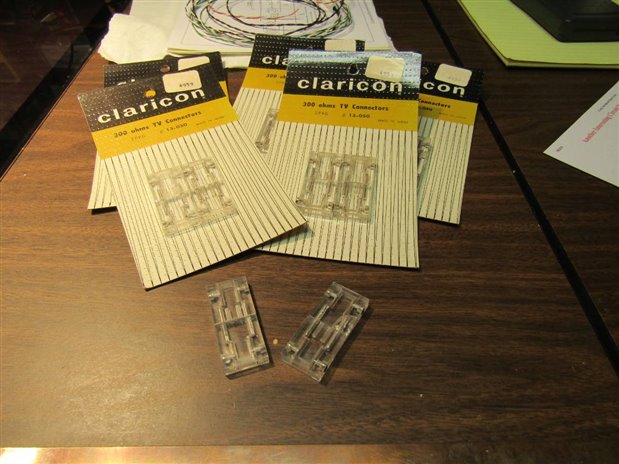
Well at $1 per card of two maybe I didn't make his day but it sure made mine.
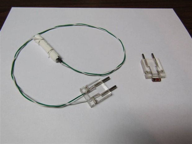
Here is a sensor with an plug attached. Based on good advice from my friends on the forum I also made a modification to the sensor. I added additional paper so that the copper electrodes in the sensor do not come into direct contact with any of the salt paper. I would not bet on this sensor being the final design but my curiosity will at least let them ride until they fail and shut off my water while I shower or worse yet if they catch the boss. The plug on the right has a 47K resistor and can be used to test the sensor line by triggering the system from any given sensor position in the house. Currently there are seven sensor positions like under the water heater, under the sink, by the main water service inlet, behind the washing machine and by the house's external faucets.
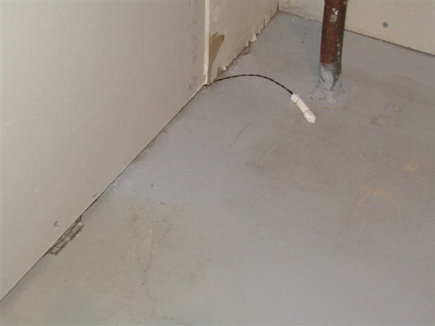
Here is a picture of the sensor that is at the water main entrance of the house. You can see the 2 pin 300 ohm inline connector tucked under the wall board.
This Chapter has gotten fairly long so I will stop for now and write one more final chapter in a couple days or as soon as I can get my video production crew, the boss Millie, to hold the camera. In the video I will put drops of water on a sensor in front of the control and mechanics to demonstrate the operation of the system.
John
Top Comments
-

kulky64
-
Cancel
-
Vote Up
0
Vote Down
-
-
Sign in to reply
-
More
-
Cancel
-

jw0752
in reply to kulky64
-
Cancel
-
Vote Up
0
Vote Down
-
-
Sign in to reply
-
More
-
Cancel
-

kulky64
in reply to jw0752
-
Cancel
-
Vote Up
0
Vote Down
-
-
Sign in to reply
-
More
-
Cancel
-

jw0752
in reply to kulky64
-
Cancel
-
Vote Up
0
Vote Down
-
-
Sign in to reply
-
More
-
Cancel
Comment-

jw0752
in reply to kulky64
-
Cancel
-
Vote Up
0
Vote Down
-
-
Sign in to reply
-
More
-
Cancel
Children