


The computer in my lab is very important to me. This of course is very subjective as its contents and utilities are understood and utilized only be me and so someday, when I can no longer use it, it will go directly from my lab to the computer recycle facility. In the meantime I do everything in my power to keep it clean, backed up, and with a protected UPS power supply. The original battery of the 650 Watt UPS is long since failed and when it did I bought a car battery and rewired things so that I can monitor the voltage of the battery and the discharge rate when it is being used.
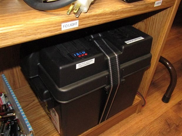
Here is the battery in its case with the volt/ammeter mounted in the cover. Every couple months I pull the mains electrical plug and let the system run for an hour or so. Two nights ago I performed this routine test but within 10 minutes the UPS was beeping frantically for power and before I could get to the mains plug it died.
I took the battery case and opened it to find that while I was checking everything else I had not been monitoring the water level of the battery and 3 years of constant float charging had finally dropped the fluid level to about an inch of the bottom. This is not a good situation and there was not much else to do except to replace the battery. This time I got a battery with ADM maintenance free technology and an 8 year warranty. We will see how that goes.
I am not one to give up too easily and my thoughts went to the possibility of resurrecting the old battery. Just to show how bad the water situation had gotten the battery took almost 3 liters of distilled water before it was full again. I put the battery on a small charger and left it to charge.
The next problem that caught my attention was how I was going to test and measure the health of the car battery. When I have this problem with small batteries I hook them up to the Process Duration Timer
Short video of the Process Duration Timer (PDT) unit in operation. You can also search on this site for the original 4 blog series if you want to know more about the Process Duration Timer build.
The size of this battery however seemed likely to strain my present test abilities. One thought that seemed to make sense was that I would use a spare UPS Backup unit with a 75 Watt incandescent bulb and use that for the load. The next problem would be how to interface the PDT to the system so that I could time the draining of the battery until the shut off voltage (which I didn't know) of the UPS was reached.
This was the inspiration that I needed to build an Interface for the PDT. As it sits the Process Duration Timer (PDT) was designed to monitor and time a voltage level and respond by stopping the clock when the monitored voltage level drops below a given threshold.
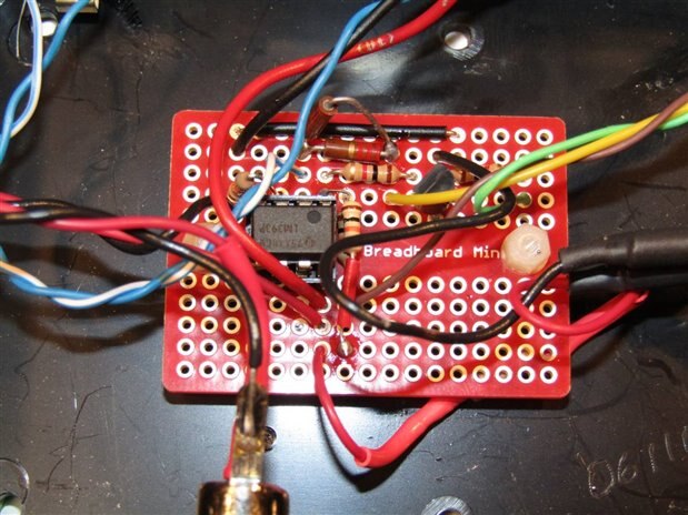
At its core the Interface is very simple with an LM393 comparitor, a MOSFET output and the required resistors and hardware needed to allow a sensor to monitor a given process by watching other physical changes in the system and reporting back to the PDT with a High or Low voltage output which in turn is used to stop the timing of the process.
Here is a schematic for the Interface:

It was my plan to build the Interface and let its ability to monitor a light level watch the 75 Watt bulb on the output of the UPS that was being powered by the damaged battery. As long as the bulb was lit the interface would send 15 volts to the PDT and it would happily keep on timing the process of battery discharge. As soon as the battery level dropped below critical for the UPS operation however the bulb would go out and the interface would send a Low voltage signal to the PDT and the timer would stop and wait for me to return and read its output.
Before I get to the actual battery test however here are some picture of the Interface:
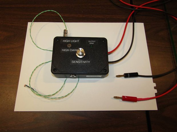
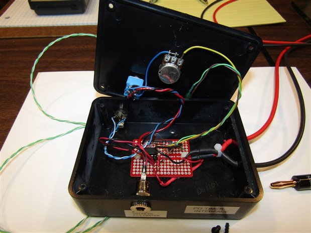
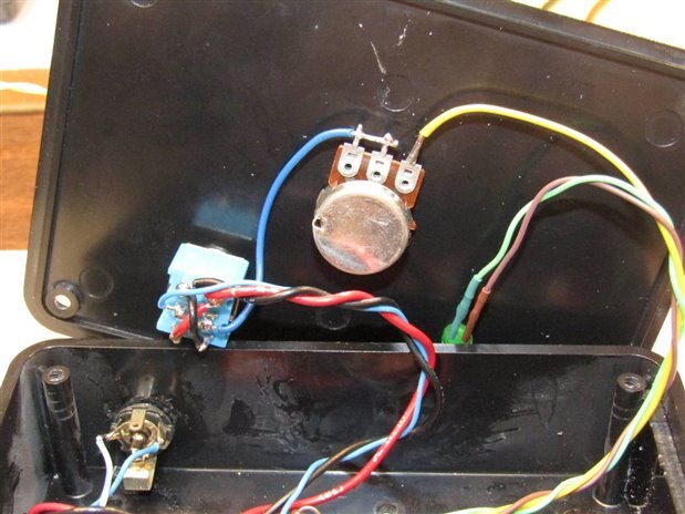
I am using a DPDT toggle switch on the unit to give me the flexibility to transition from High output to Low output on the Interface in either direction, Light to Dark, or Dark to Light. The LED tells the state of the output and the potentiometer allows the operator to adjust the sensitivity to fit local light conditions.

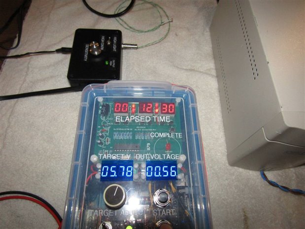
Here is a picture of the experiment set up. The battery has been charged for several hours and is showing all the signs that it is bad. The UPS is hooked to the battery and has a 75 Watt bulb plugged into one of its outlets. In a preparatory experiment I have measured the current demand on the battery to power the 75 Watt bulb. This turned out to be about 8.5 Amps. For some reason I don't understand right now the UPS's power demand is not stable but fluctuates +/- 1 amp while it is working. If anyone knows why please clue me in. The photo resistor sensor of the PDT Interface is pointed towards the 75 watt bulb. The Interface is set so that the output will transition from High output to Low output when the sensor no longer sees the light.
The PDT has been set to watch the Interface which should put out about 14.86 volts and continue timing the process until it sees less than 5.81 Volts.

The timer indicates that we are 1 minute 23 seconds into the test at this point.
We really did not have long to wait as 12 minutes and 30 seconds after the process started the battery gave up. If we do the math for 8.5 Amps over 12 minutes and 30 seconds we get about 1.7 Ah of power. For a battery that should have upwards of 45 Amp Hours this is a clear indication that the low fluid level has permanently damaged this battery beyond redemption.
Since I was still in the mood to upgrade the Interface I also made a Thermistor Sensor for it. The thermistor was chosen to work with the Interface in the range of 40 C to 130 C as I guessed that this might be a range that would be usable for me. Now I will be able to monitor and time processes that involve things that gradually heat up or cool down.
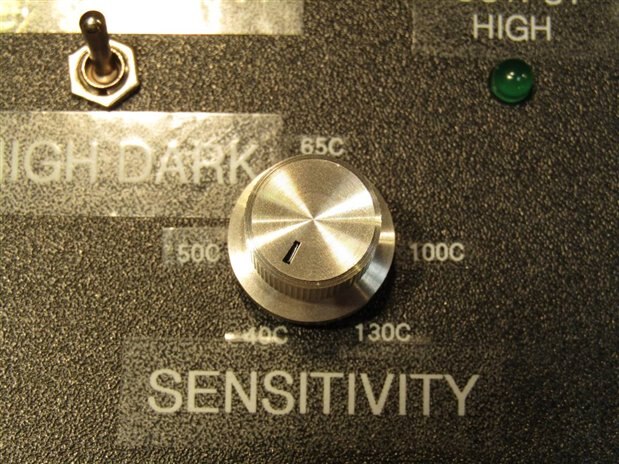
The sensitivity control was labeled with approximate transition temperatures for future use of the thermistor sensor.
Overall I am pleased with the added flexibility of the PDT that the Interface has provided. It is the silver lining of the cloud that was the failure of the backup battery.
John
Top Comments