element14 Community
element14 Community
    Register Log In
  • Site
  • Search
  • Log In Register
  • Community Hub
    Community Hub
    • What's New on element14
    • Feedback and Support
    • Benefits of Membership
    • Personal Blogs
    • Members Area
    • Achievement Levels
  • Learn
    Learn
    • Ask an Expert
    • eBooks
    • element14 presents
    • Learning Center
    • Tech Spotlight
    • STEM Academy
    • Webinars, Training and Events
    • Learning Groups
  • Technologies
    Technologies
    • 3D Printing
    • FPGA
    • Industrial Automation
    • Internet of Things
    • Power & Energy
    • Sensors
    • Technology Groups
  • Challenges & Projects
    Challenges & Projects
    • Design Challenges
    • element14 presents Projects
    • Project14
    • Arduino Projects
    • Raspberry Pi Projects
    • Project Groups
  • Products
    Products
    • Arduino
    • Avnet & Tria Boards Community
    • Dev Tools
    • Manufacturers
    • Multicomp Pro
    • Product Groups
    • Raspberry Pi
    • RoadTests & Reviews
  • About Us
  • Store
    Store
    • Visit Your Store
    • Choose another store...
      • Europe
      •  Austria (German)
      •  Belgium (Dutch, French)
      •  Bulgaria (Bulgarian)
      •  Czech Republic (Czech)
      •  Denmark (Danish)
      •  Estonia (Estonian)
      •  Finland (Finnish)
      •  France (French)
      •  Germany (German)
      •  Hungary (Hungarian)
      •  Ireland
      •  Israel
      •  Italy (Italian)
      •  Latvia (Latvian)
      •  
      •  Lithuania (Lithuanian)
      •  Netherlands (Dutch)
      •  Norway (Norwegian)
      •  Poland (Polish)
      •  Portugal (Portuguese)
      •  Romania (Romanian)
      •  Russia (Russian)
      •  Slovakia (Slovak)
      •  Slovenia (Slovenian)
      •  Spain (Spanish)
      •  Sweden (Swedish)
      •  Switzerland(German, French)
      •  Turkey (Turkish)
      •  United Kingdom
      • Asia Pacific
      •  Australia
      •  China
      •  Hong Kong
      •  India
      •  Korea (Korean)
      •  Malaysia
      •  New Zealand
      •  Philippines
      •  Singapore
      •  Taiwan
      •  Thailand (Thai)
      • Americas
      •  Brazil (Portuguese)
      •  Canada
      •  Mexico (Spanish)
      •  United States
      Can't find the country/region you're looking for? Visit our export site or find a local distributor.
  • Translate
  • Profile
  • Settings
Personal Blogs
  • Community Hub
  • More
Personal Blogs
John Wiltrout's Blog Experimenting with an Isotek Kelvin Resistor
  • Blog
  • Documents
  • Mentions
  • Sub-Groups
  • Tags
  • More
  • Cancel
  • New
  • Share
  • More
  • Cancel
Group Actions
  • Group RSS
  • More
  • Cancel
Engagement
  • Author Author: jw0752
  • Date Created: 21 Mar 2016 5:55 AM Date Created
  • Views 839 views
  • Likes 5 likes
  • Comments 12 comments
  • current_sense_resistors
  • kelvin_resistor
Related
Recommended

Experimenting with an Isotek Kelvin Resistor

jw0752
jw0752
21 Mar 2016

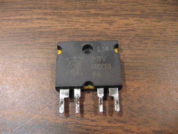
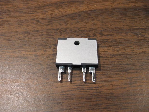
Today I salvaged out a circuit board from an ESPE Dental Cure light. To my delight there was Kelvin precision resistor on the board. Specifically it was an Isotek PBV R033 which is a heat sink mounted 10 Watt Kelvin resistor with a value of 0.033 Ohms 1%. Here are front and back photos of the device. I first learned about these resistors a couple years ago from one of the great tutorials posted by Robert Peter Oakes on building power supplies.


image


image


Now in the big scheme of things the arrival of a real 4 terminal Kelvin resistor to my bench must seem pretty trivial but this is my first. Yes in 55 + years of tearing equipment and circuit boards apart this is the first time I have had a Kelvin Resistor to test out. What follows is an exercise in simplicity but it is the type of experiment that must be performed on the occasion when something new shows up. In case you would like more information on this particular resistor here is a link to the company data sheet:


http://www.isotekcorp.com/sites/default/files/sites/default/files/pdfs/PBV.pdf


I began by producing a new custom symbol for my schematic drawing program. I always like to produce a schematic before an experiment even if it is fairly simple like this one. Here is a copy of the schematic for the test setup:


image


My plan was to power the circuit at 4 different current levels and take readings of the Current (I), the voltage of the source (Vs), and the voltage across the Kelvin Resistor (Vkr). I would then use my empirical numbers to calculate the resistance (Rk) of the Kelvin Resistor and compare the calculations to the nominal value of 0.033 Ohms 1%. The readings for the voltage of the source would not figure into the calculations but I like to have them for an overview of the system. Keep in mind that perhaps the most accurate instrument in my shop is a Fluke 177 which will be used for DC current readings. Basically none of my equipment qualifies as precision just practical for my level of endeavor. The other equipment that will be used for this experiment are a Mastech power supply which will be the current source and a Radio Shack digital meter that will read the voltage at the test terminals of the Kelvin resistor. The final digit of the Radio Shack meter will read 0.1 mV.  In the chart that follows I have listed the calculated values of (Rk) to several magnitudes of precision past the point justifiable by the precision of the instruments. This was done only to give a better feel for the proximity of the results to the nominal value of (Rk). Ohams Law V = I x R was the basis for the calculations.  Here is the test setup that I used:


image


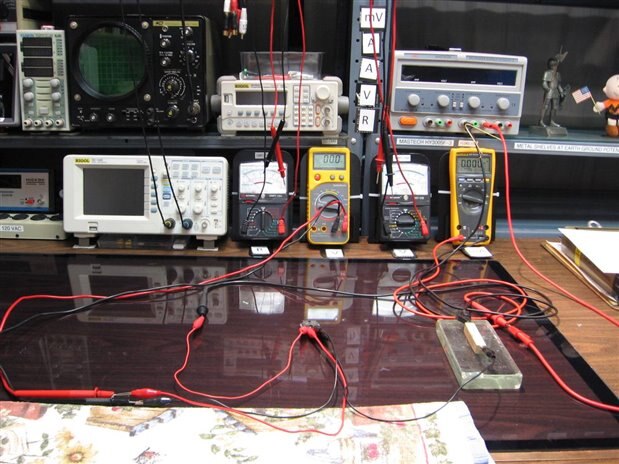
The resistor resting on the glass block is a 2 ohm 25 W resistor that is being used as a load. When the circuit was fully powered at 1 Amp the dissipation required was about 2.7 watts. This resistor does not figure into our calculations either.


image


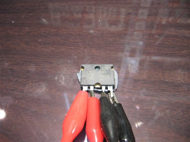
While not necessary for this experiment, if everything runs smoothly, the Kelvin resistor was stuck to the glass desk top to serve as a heat sink. The Kelvin resistor can dissipate 3 Watts in free air and 10 Watts when properly heat sunk. Since things do not always run smoothly on my bench I try not to take chances hence the heat sinking. Here is the data that was collected from the experiment:


image


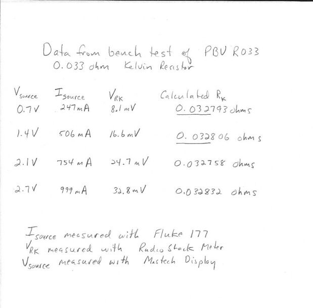
The nominal value of the Kelvin Resistor is 0.033 Ohms with a 1% tolerance. This means that the actual value should lie between 0.03267 and 0.03333 Ohms. I am pleased that my calculated results also fall within that 1 % range. I will now put the new Kelvin resistor aside for use in my next power supply build.

  • Sign in to reply

Top Comments

  • mcb1
    mcb1 over 9 years ago +2
    Excellent blog and demonstration how to use simple equipment to validate the test.
  • shabaz
    shabaz over 9 years ago +2
    Hi John, Nice find and analysis! At first glance I would have mistaken it for a bridge rectifier. Also, what a cool idea to have the labels to make it clear what each meter is being used for. I was looking…
  • clem57
    clem57 over 9 years ago +1
    Nice find! But after reading, the four posts are not clear. I see the outer two you put the load and the inside I see the v=ir with a voltage meter? Clem PS How common are resistors over 1 mega ohm? I…
  • jw0752
    jw0752 over 9 years ago in reply to DAB

    HI DAB,

    I find salvaging an old circuit board, relaxing and often very educational. Thanks for your comment.

    John

    • Cancel
    • Vote Up +1 Vote Down
    • Sign in to reply
    • More
    • Cancel
  • DAB
    DAB over 9 years ago

    Great blog John.


    I had never encountered a kelvin resistor in my career, so reading about you find and test was very enlightening.


    Once again you are sparking my interests in looking into older equipment to see what goodies might lay within.


    Well done.


    DAB

    • Cancel
    • Vote Up +1 Vote Down
    • Sign in to reply
    • More
    • Cancel
  • Robert Peter Oakes
    Robert Peter Oakes over 9 years ago in reply to clem57

    R is the Kelvin Resistor, if you want a load int he circuit then it would be in series with one of the outer loops where it will not interfere with the measurement of the Kelvin Resistor

    • Cancel
    • Vote Up +1 Vote Down
    • Sign in to reply
    • More
    • Cancel
  • jw0752
    jw0752 over 9 years ago in reply to clem57

    Hi Clem,

    No in Peter's drawing there is no load per se. The R subject is the Kelvin Resistor. If you are using a current source then technically you do not need another load to limit it as I did. I put it in to make it a more practical circuit as any practical circuit would have a load that the current would be working through as well as the sense resistor (Kelvin resistor).

    John

    • Cancel
    • Vote Up 0 Vote Down
    • Sign in to reply
    • More
    • Cancel
  • clem57
    clem57 over 9 years ago in reply to Robert Peter Oakes

    So R subject is the load. Right?

    • Cancel
    • Vote Up 0 Vote Down
    • Sign in to reply
    • More
    • Cancel
>
element14 Community

element14 is the first online community specifically for engineers. Connect with your peers and get expert answers to your questions.

  • Members
  • Learn
  • Technologies
  • Challenges & Projects
  • Products
  • Store
  • About Us
  • Feedback & Support
  • FAQs
  • Terms of Use
  • Privacy Policy
  • Legal and Copyright Notices
  • Sitemap
  • Cookies

An Avnet Company © 2025 Premier Farnell Limited. All Rights Reserved.

Premier Farnell Ltd, registered in England and Wales (no 00876412), registered office: Farnell House, Forge Lane, Leeds LS12 2NE.

ICP 备案号 10220084.

Follow element14

  • X
  • Facebook
  • linkedin
  • YouTube