


A while back I heard that a diode full wave bridge could be replaced with MOSFETs that were switched in the proper sequence. The advantage of doing this would be the very low Rds(on) available from the MOSFETs which results in much lower waste heat generation and more power delivered to the load. For this experiment I am going to use the Linear Technologies LT4320 controller and (4) IRLZ34 N channel MOSFETs. I will also set up a conventional diode bridge and compare the readings that I get from each system. Here is a link to the data sheet for the LT4320:
http://www.farnell.com/datasheets/1804288.pdf?_ga=1.70622352.1418853850.1451543312
Here is a simple schematic from the data sheet for how the LT4320 connects to the MOSFETs

While the LT4320-1 is capable to 600 Hz the chip I am using is the LT4320 and it is rated for up to 60 Hz operation.
I will begin by constructing a simple full wave bridge using a common 4 diode package and take some readings. I have also installed a 680 uF capacitor across the output.

The transformer in the picture has been connected to a variac and the output has been dialed to 25.75 Volts AC under load. This may appear a bit arbitrary but when the variac you are using isn't precision you take the first stable value that is close to the desired value. I have loaded the circuit with (4) 12 volt auto tail light bulbs in series. With this load we measure the DC output of the system at 27.97 Volts DC and the current is 390 mA.

The AC ripple on the voltage is 2.68 Volts.

Here is what the wave form across one junction looks like:
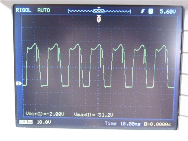
The next step in the experiment was to wire up the LT4320 and the (4) MOSFETs. While the schematic looks very simple it turned out to be rather more complicated. In the end I used wire jumpers instead of the more solid staple connectors. It is likely that this will result in a higher connection resistance and will lower the performance difference that I hope to observe. Here are a couple pictures of the circuit:


The MOSFET circuit performed very nicely. Once again our input voltage under load was 25.75 VAC. The output voltage of the system into the load was 29.5 Volts DC and despite the lighter wiring we had a current of 400 mA. The ripple of the MOSFET system was also 2.68 VAC. Here are shots of the meters and the oscilloscope screens for the ripple and across the drain - source on one MOSFET.


In both experimental setups I monitored the temperature of the devices with the finger tip thermometer. The diode bridge got almost hot to the touch while the MOSFETS remained cool. This was not very scientific and may also be explained but the much larger surface area of the MOSFETs compared to the Diode Bridge. Here are the data from the two experiments side by side.
Diode Bridge LT4320 & MOSFETs
Input Voltage 25.75 VAC 60 Hz 25.75 VAC 60 Hz
Output Voltage 27.95 V DC 29.4 V DC
Ripple 2.68 V PP 2.68 V PP
Load Current 390 mA 400 mA
The MOSFET Ideal Diode Bridge using the LT4320 controller seems to be a much better system for rectification as it delivers more power to the load and has less heat generated. Keep in mind that the LT4320 and MOSFETs still showed an improvement despite being wired with the higher resistance jumper wires. On the other hand the complexity of the circuit and the magnitude higher cost over the diode bridge will not make this a practical replacement in most applications.
John
Top Comments