element14 Community
element14 Community
    Register Log In
  • Site
  • Search
  • Log In Register
  • Community Hub
    Community Hub
    • What's New on element14
    • Feedback and Support
    • Benefits of Membership
    • Personal Blogs
    • Members Area
    • Achievement Levels
  • Learn
    Learn
    • Ask an Expert
    • eBooks
    • element14 presents
    • Learning Center
    • Tech Spotlight
    • STEM Academy
    • Webinars, Training and Events
    • Learning Groups
  • Technologies
    Technologies
    • 3D Printing
    • FPGA
    • Industrial Automation
    • Internet of Things
    • Power & Energy
    • Sensors
    • Technology Groups
  • Challenges & Projects
    Challenges & Projects
    • Design Challenges
    • element14 presents Projects
    • Project14
    • Arduino Projects
    • Raspberry Pi Projects
    • Project Groups
  • Products
    Products
    • Arduino
    • Avnet & Tria Boards Community
    • Dev Tools
    • Manufacturers
    • Multicomp Pro
    • Product Groups
    • Raspberry Pi
    • RoadTests & Reviews
  • About Us
  • Store
    Store
    • Visit Your Store
    • Choose another store...
      • Europe
      •  Austria (German)
      •  Belgium (Dutch, French)
      •  Bulgaria (Bulgarian)
      •  Czech Republic (Czech)
      •  Denmark (Danish)
      •  Estonia (Estonian)
      •  Finland (Finnish)
      •  France (French)
      •  Germany (German)
      •  Hungary (Hungarian)
      •  Ireland
      •  Israel
      •  Italy (Italian)
      •  Latvia (Latvian)
      •  
      •  Lithuania (Lithuanian)
      •  Netherlands (Dutch)
      •  Norway (Norwegian)
      •  Poland (Polish)
      •  Portugal (Portuguese)
      •  Romania (Romanian)
      •  Russia (Russian)
      •  Slovakia (Slovak)
      •  Slovenia (Slovenian)
      •  Spain (Spanish)
      •  Sweden (Swedish)
      •  Switzerland(German, French)
      •  Turkey (Turkish)
      •  United Kingdom
      • Asia Pacific
      •  Australia
      •  China
      •  Hong Kong
      •  India
      • Japan
      •  Korea (Korean)
      •  Malaysia
      •  New Zealand
      •  Philippines
      •  Singapore
      •  Taiwan
      •  Thailand (Thai)
      • Vietnam
      • Americas
      •  Brazil (Portuguese)
      •  Canada
      •  Mexico (Spanish)
      •  United States
      Can't find the country/region you're looking for? Visit our export site or find a local distributor.
  • Translate
  • Profile
  • Settings
Personal Blogs
  • Community Hub
  • More
Personal Blogs
John Wiltrout's Blog Exploring the Recom RH-2405D
  • Blog
  • Documents
  • Mentions
  • Sub-Groups
  • Tags
  • More
  • Cancel
  • New
  • Share
  • More
  • Cancel
Group Actions
  • Group RSS
  • More
  • Cancel
Engagement
  • Author Author: jw0752
  • Date Created: 10 Nov 2018 5:22 AM Date Created
  • Views 1541 views
  • Likes 8 likes
  • Comments 13 comments
  • bench_power_supply
  • recom_rh
Related
Recommended

Exploring the Recom RH-2405D

jw0752
jw0752
10 Nov 2018

My latest experiments revolve around using the Chinese linear power supply board that has been the heart of many of my bench supply builds but rather than powering it with the tradition transformer and bridge arrangement I want to power it with a switch mode power supply.


Here is a schematic of the linear power supply board as supplied from the vendor:


image


My enthusiasm often gets ahead of my eyes and my brain so in typical form I assembled a board and left off the bridge diodes. I then hooked up a 28 volt power supply and checked to see if it would work. It did not! Digging out my schematics with annotated voltages I quickly realized that the important negative 5 volt supply rail was missing. A look at the schematic revealed that the negative 5 volt rail was generated by the AC input line being fed by way of R2 and C2 to a voltage inverter circuit made up of D5, D6, and C3. This voltage is then regulated by R3 and D7.  Subsequent experiments showed that this negative 5 volt rail supplies about 8 mA of current to the negative supply pins (4) of the TL081 Op Amps at U2 and U3.


I was left with the problem of supplying the negative 5 volts from the expected 28 volt output of the SMPS that I hoped to use to drive this board.


I have been using Recom switching regulators quite often in my builds so I went to their site and started looking for a device that would take 28 volts input and give me a negative 5 volts out. Here is a data sheet for the the device, a RH 2405D, which most closely matched my needs:


https://datasheet.octopart.com/RH-2405D-H6-Recom-Power-datasheet-68303594.pdf


The input rating on this converter is 24 Volts +/- 10% which would not get me quite to the 28 Volts that I expected from the SMPS. This problem was easily solved as the Chinese linear power supply board comes with a LM7824 that is to be used to power a heat sink cooling fan. I will use the fan supply to power the RH-2405 pending a successful testing of the RH-2405.


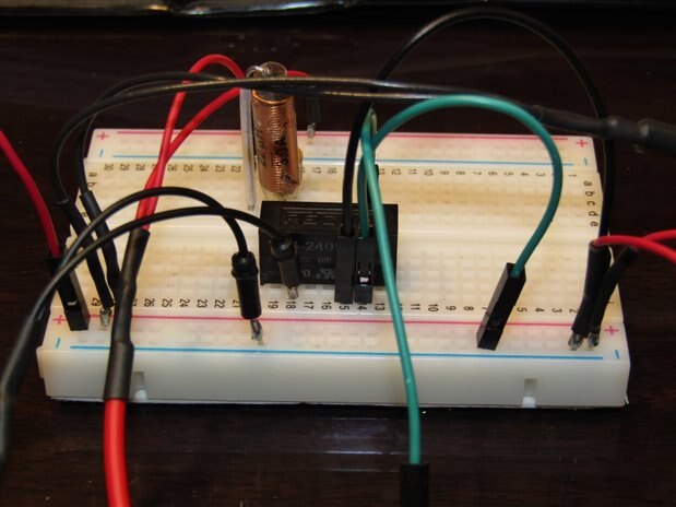
Once the RH-2405 arrived I set to checking it out and bread boarding it into a test circuit.:


imageimage


Here are the questions that I wanted to answer with my experiment:


Will it work as advertised?

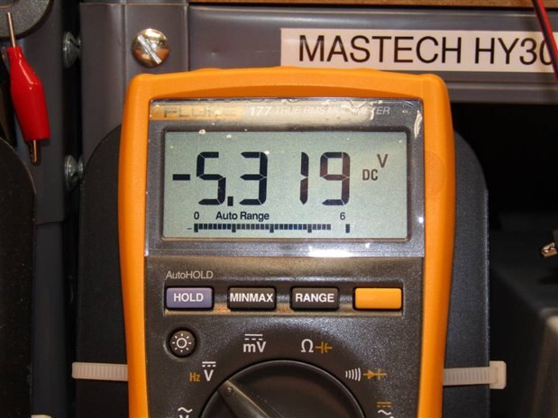
Are the +/- 5 volt outputs and their common isolated as advertised?

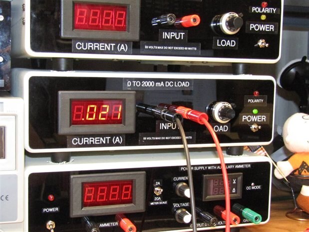
How will a load affect the operation and voltage of the outputs?

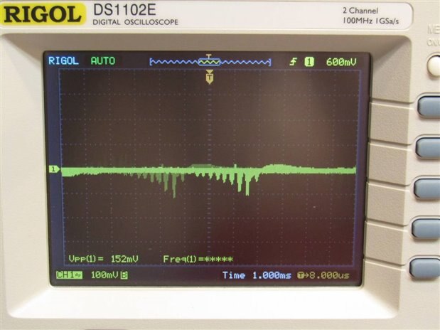
What will the ripple on the output look like?


The experiment showed that the isolation of the outputs was good and able to be connected as needed to produce a negative 5 volt rail for the Chinese PS board. I hooked up a load and ran it up to 21 mA which is over double what is expected in normal operation if it were used on the linear board. The ripple on the output looked to be around 150 mV. Here are photos of the test equipment as it monitored the experiment.


image


image


image


All the tests went satisfactorily and I am now prepared to depopulate one of the Chinese Linear board of the original components that generated the negative 5 volt rail and hack the RH-2405 converter onto the board in their place. In preparation for this the original schematic was also depopulated and redrawn with the 24 volt regulator and the RH-2405. Here is the modified schematic:


image


Sounds like a good project for tomorrow night.


John

  • Sign in to reply

Top Comments

  • Jan Cumps
    Jan Cumps over 7 years ago in reply to jw0752 +4
    John, I may be mistaken, but I don’t see any filtering on the -5 V rail. There’s switching going on inside the RH component and I expect that you see the artifacts of that switching on your rail. I just…
  • jw0752
    jw0752 over 7 years ago in reply to jc2048 +4
    Hi Jon, Pretty funny that I can't remember my own blogs. It seems I had a component that I could have used without placing an order but it hasn't hurt me to do a little exploring. What I can't figure out…
  • Jan Cumps
    Jan Cumps over 7 years ago in reply to jw0752 +4
    John, have you ever tried to use Rigol's UltraSigma software for your oscilloscope? It allows you to take a perfect screen capture from your computer. Easy to use. Connect the scope with USB. Open UltraSigma…
Parents
  • Jan Cumps
    Jan Cumps over 7 years ago

    In our electronic load, we use a LM2662LM2662. It's cheaper and doesn't need an external inductor.

    image


    edit: the unit of the inductor in your schematic is uF. Shouldn’t it be uH?

    edit2: does the fan need regulated voltage? Could you tap that one off before the regulator? Asking because it will cause most of the heat in the regulator. If the 28 V is too high for the fan, a few diodes in series can drop the voltage.

    • Cancel
    • Vote Up +3 Vote Down
    • Sign in to reply
    • More
    • Cancel
  • jw0752
    jw0752 over 7 years ago in reply to Jan Cumps

    Hi Jan,


    Thanks for the critical look at what I did.  I will order in an LM 2662 to take a look at it. There was no particular reason why I chose a RH-2405 for the component. The inductor isn't needed in the circuit for operation but was listed as an EMI surpressor. Yes the units on the inductor should be uH. I use inductors so infrequently compared to capacitors I guess my mind was locked into the wrong units. No the fan probably doesn't need regulated voltage. I doubt that the difference between the 28 volt supply and the regulated 24 means much to it. It is just how they designed it and sometimes I don't sufficiently question what is already there. It is a tiny fan and has only like 30 mA draw so the current times the voltage drop is only about 120 mW.


    I have a question to bounce back to you. Why is it that it is so hard to improve the ripple on the output? I would expect a decoupling capacitor to absorb the ripple and improve the output but it doesn't seem to help even under no load except the scopes probe. This is a question that I have encountered many times and this is a good opportunity to ask it.


    John

    • Cancel
    • Vote Up +3 Vote Down
    • Sign in to reply
    • More
    • Cancel
  • Jan Cumps
    Jan Cumps over 7 years ago in reply to jw0752

    John, I may be mistaken, but I don’t see any filtering on the -5 V rail.

    There’s switching going on inside the RH component and I expect that you see the artifacts of that switching on your rail.


    I just checked the specs and these components can have up to 120 mV ripple. You could put a lower than 330 uF capacitor over the -5 V rail.

    • Cancel
    • Vote Up +4 Vote Down
    • Sign in to reply
    • More
    • Cancel
  • jw0752
    jw0752 over 7 years ago in reply to Jan Cumps

    Hi Jan,


    I went back to the bread board and conducted some experiments to see if I could affect the ripple. Thanks to your suggestions and some luck I was able to drastically improve it. Here is the amended schematic:


    image


    The changes that made a big difference were the inclusion of a 330 uF capacitor on the input of the RH-2405. Putting it on the negative 5 volt rail had almost no effect. Also a 1 uF ceramic on the negative 5 volt rail also had a measurable effect. Here is a photo of the oscilloscope reading of the rail after the changes were made.


    image


    This looks like a 1 order of magnitude improvement to me. It surprised me that the bulk of the problem was coming from the input side. This may not have been a serious contributor on the circuit board as the supply voltage rail would have been shorter and more robust. On the bread board however I have 3 feet of medium gauge jumper wire back to the power supply. In any case I am pleased with the improvement and once again thank you for taking the time to give me some great insights.


    John

    • Cancel
    • Vote Up +3 Vote Down
    • Sign in to reply
    • More
    • Cancel
  • jc2048
    jc2048 over 7 years ago in reply to jw0752

    I will order in an LM 2662 to take a look at it.

    If you want some inspiration, here's a blog someone has done with a similar part


    Putzing with a MAXIM ICL7662 Voltage Converter

    • Cancel
    • Vote Up +3 Vote Down
    • Sign in to reply
    • More
    • Cancel
  • jw0752
    jw0752 over 7 years ago in reply to jc2048

    Hi Jon,


    Pretty funny that I can't remember my own blogs. It seems I had a component that I could have used without placing an order but it hasn't hurt me to do a little exploring. What I can't figure out is how you remembered this old blog from 2016. As soon as I saw the title I was suspicious that it was me or someone with a similar blog naming thought process.


    I learn many things day by day but it is a constant struggle to retain them so that they are available when needed. I use a variety of cataloging and organizational tools but still I have to spend a lot of time relearning and retracing the same steps.


    Thanks for the smile.


    John

    • Cancel
    • Vote Up +4 Vote Down
    • Sign in to reply
    • More
    • Cancel
Comment
  • jw0752
    jw0752 over 7 years ago in reply to jc2048

    Hi Jon,


    Pretty funny that I can't remember my own blogs. It seems I had a component that I could have used without placing an order but it hasn't hurt me to do a little exploring. What I can't figure out is how you remembered this old blog from 2016. As soon as I saw the title I was suspicious that it was me or someone with a similar blog naming thought process.


    I learn many things day by day but it is a constant struggle to retain them so that they are available when needed. I use a variety of cataloging and organizational tools but still I have to spend a lot of time relearning and retracing the same steps.


    Thanks for the smile.


    John

    • Cancel
    • Vote Up +4 Vote Down
    • Sign in to reply
    • More
    • Cancel
Children
  • fmilburn
    fmilburn over 7 years ago in reply to jw0752


    I learn many things day by day but it is a constant struggle to retain them so that they are available when needed.


    That is pretty funny. You are not alone :-)

    • Cancel
    • Vote Up +2 Vote Down
    • Sign in to reply
    • More
    • Cancel
  • genebren
    genebren over 7 years ago in reply to jw0752

    Funny yes, and you are by no means the only one(s) ! (Now what were we talking about????)

    Gene

    • Cancel
    • Vote Up +2 Vote Down
    • Sign in to reply
    • More
    • Cancel
element14 Community

element14 is the first online community specifically for engineers. Connect with your peers and get expert answers to your questions.

  • Members
  • Learn
  • Technologies
  • Challenges & Projects
  • Products
  • Store
  • About Us
  • Feedback & Support
  • FAQs
  • Terms of Use
  • Privacy Policy
  • Legal and Copyright Notices
  • Sitemap
  • Cookies

An Avnet Company © 2025 Premier Farnell Limited. All Rights Reserved.

Premier Farnell Ltd, registered in England and Wales (no 00876412), registered office: Farnell House, Forge Lane, Leeds LS12 2NE.

ICP 备案号 10220084.

Follow element14

  • X
  • Facebook
  • linkedin
  • YouTube