element14 Community
element14 Community
    Register Log In
  • Site
  • Search
  • Log In Register
  • About Us
  • Community Hub
    Community Hub
    • What's New on element14
    • Feedback and Support
    • Benefits of Membership
    • Personal Blogs
    • Members Area
    • Achievement Levels
  • Learn
    Learn
    • Ask an Expert
    • eBooks
    • element14 presents
    • Learning Center
    • Tech Spotlight
    • STEM Academy
    • Webinars, Training and Events
    • Learning Groups
  • Technologies
    Technologies
    • 3D Printing
    • FPGA
    • Industrial Automation
    • Internet of Things
    • Power & Energy
    • Sensors
    • Technology Groups
  • Challenges & Projects
    Challenges & Projects
    • Design Challenges
    • element14 presents Projects
    • Project14
    • Arduino Projects
    • Raspberry Pi Projects
    • Project Groups
  • Products
    Products
    • Arduino
    • Avnet Boards Community
    • Dev Tools
    • Manufacturers
    • Multicomp Pro
    • Product Groups
    • Raspberry Pi
    • RoadTests & Reviews
  • Store
    Store
    • Visit Your Store
    • Choose another store...
      • Europe
      •  Austria (German)
      •  Belgium (Dutch, French)
      •  Bulgaria (Bulgarian)
      •  Czech Republic (Czech)
      •  Denmark (Danish)
      •  Estonia (Estonian)
      •  Finland (Finnish)
      •  France (French)
      •  Germany (German)
      •  Hungary (Hungarian)
      •  Ireland
      •  Israel
      •  Italy (Italian)
      •  Latvia (Latvian)
      •  
      •  Lithuania (Lithuanian)
      •  Netherlands (Dutch)
      •  Norway (Norwegian)
      •  Poland (Polish)
      •  Portugal (Portuguese)
      •  Romania (Romanian)
      •  Russia (Russian)
      •  Slovakia (Slovak)
      •  Slovenia (Slovenian)
      •  Spain (Spanish)
      •  Sweden (Swedish)
      •  Switzerland(German, French)
      •  Turkey (Turkish)
      •  United Kingdom
      • Asia Pacific
      •  Australia
      •  China
      •  Hong Kong
      •  India
      •  Korea (Korean)
      •  Malaysia
      •  New Zealand
      •  Philippines
      •  Singapore
      •  Taiwan
      •  Thailand (Thai)
      • Americas
      •  Brazil (Portuguese)
      •  Canada
      •  Mexico (Spanish)
      •  United States
      Can't find the country/region you're looking for? Visit our export site or find a local distributor.
  • Translate
  • Profile
  • Settings
Personal Blogs
  • Community Hub
  • More
Personal Blogs
John Wiltrout's Blog Playing with an OP 191 Op Amp
  • Blog
  • Documents
  • Mentions
  • Sub-Groups
  • Tags
  • More
  • Cancel
  • New
  • Share
  • More
  • Cancel
Group Actions
  • Group RSS
  • More
  • Cancel
Engagement
  • Author Author: jw0752
  • Date Created: 22 Jan 2016 7:42 AM Date Created
  • Views 2264 views
  • Likes 5 likes
  • Comments 12 comments
  • op191_op_amp
Related
Recommended

Playing with an OP 191 Op Amp

jw0752
jw0752
22 Jan 2016

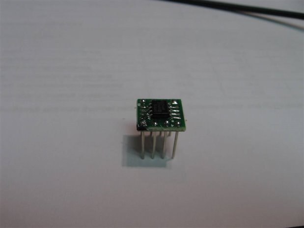
One of the really great things about the E-14 Web Site is how much one can learn just by reading and paying attention to some of the threads. On Jan 9th michaelkellett posted information on the OP191 and OP192 Op Amps which he likes to use in his designs. Being curious to play with them for myself I marked down the number and ordered some of the OP 191 for my shop. The OP191s that I received were in the SOIC8 package so it was necessary to mount it on an adapter board so that I could conduct some simple experiments on the bread boards. Here is the OP191 after I mounted it on the adapter and turned it into a DIP8.


image


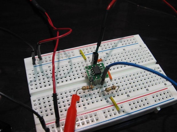
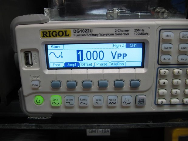
I next built a simple circuit with a gain of 10 and used my wave form generator and my oscilloscope to look at the limits of the chip and how well it performed. Here is the simple circuit.


image


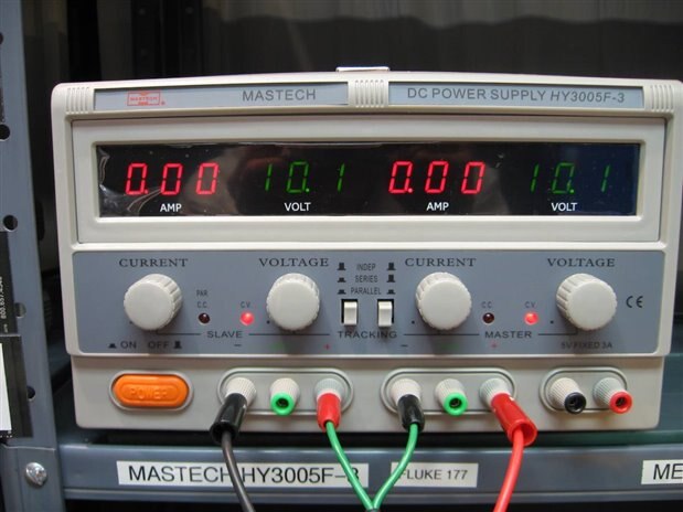
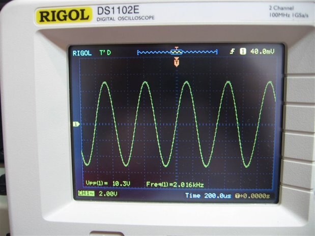
I used a +/- 10 volt supply for the chip and I ran the input level down until I could no longer get good readings on my scope. I was very impressed with how well the OP191 worked. Actually it doesn't take that much to impress me or to cover my needs. I could have taken michaelkellett 's word for it but what would have been the fun in that? The Op Amp did a very good job reproducing sine, square, and ramp inputs.


Here are the readouts of the test equipment during one of the experiments on the Op Amp.


image


image

image


Thanks again to MK for the excellent recommendation and all the fun I had tonight playing with the OP191. It will be fun to use it in my next build that requires this level of Rail to Rail Op Amp. If you want to read MK's original post it is in this thread


Power Supply for Home lab?

by mudz


John.

  • Sign in to reply

Top Comments

  • michaelkellett
    michaelkellett over 9 years ago +2
    I'm glad it's working well - I've just finished the design of a board for a client with 9 OPA192s on it - the bare boards should be here on Tuesday so I'll post some pictures (and a some bits of circuit…
  • jc2048
    jc2048 over 9 years ago in reply to jw0752 +2
    I glossed over it in my post, but there are two main effects that roll off the response at higher frequencies. One is the decline in the open loop gain, the other is the slew-rate limitation of the output…
  • jc2048
    jc2048 over 9 years ago in reply to jw0752 +2
    Your roll-off is much earlier than the datasheet would suggest (Figure 15). It's a bit difficult to read, but at a closed-loop gain = -10 their graph shows the actual gain falling by half (-6dB down) at…
Parents
  • jc2048
    jc2048 over 9 years ago

    Very nice part.


    TI have a spice model for it, so I thought I'd try your experiment virtually on my computer.


    Here's the circuit (inverting amplifier, gain of 10) with +12V and -12V supplies


    image


    And here are the waveforms, the input is 100mV peak and the output is 988.55mV peak so it works! A gain of 9.8855, so almost 10.


    image


    And here's the frequency response. The roll-off is what you'd expect from the decline in the open-loop gain at higher frequencies, so it looks at first glance like the modelling is quite good and simulation would have some use for experimenting quickly with circuit ideas and configurations.


    image

    • Cancel
    • Vote Up +1 Vote Down
    • Sign in to reply
    • More
    • Cancel
  • jw0752
    jw0752 over 9 years ago in reply to jc2048

    Hi Jon,

    I had some time so I used a +/- 12 volt supply and an input voltage of 500 mA. I then varied the frequency from 1 kHz to 500 kHz where I found the gain to be unity. Here is a graph of the output voltage P-P versus the frequency in kHz. I was not able to compare your projected graph to my output easily as yours is in db gain and has a logarithmic scale but they both seem to indicate where the drop out starts to occur. As i mentioned my cables and test equipment are likely to affect the readings as well. Here is a rough graph of what I measured.


    image


    John

    • Cancel
    • Vote Up +1 Vote Down
    • Sign in to reply
    • More
    • Cancel
Comment
  • jw0752
    jw0752 over 9 years ago in reply to jc2048

    Hi Jon,

    I had some time so I used a +/- 12 volt supply and an input voltage of 500 mA. I then varied the frequency from 1 kHz to 500 kHz where I found the gain to be unity. Here is a graph of the output voltage P-P versus the frequency in kHz. I was not able to compare your projected graph to my output easily as yours is in db gain and has a logarithmic scale but they both seem to indicate where the drop out starts to occur. As i mentioned my cables and test equipment are likely to affect the readings as well. Here is a rough graph of what I measured.


    image


    John

    • Cancel
    • Vote Up +1 Vote Down
    • Sign in to reply
    • More
    • Cancel
Children
  • jc2048
    jc2048 over 9 years ago in reply to jw0752

    I glossed over it in my post, but there are two main effects that roll off the response at higher frequencies. One is the decline in the open loop gain, the other is the slew-rate limitation of the output. How much the slew-rate affects you depends on the size of the output signal. You should be able to see which is the limiting factor at around 70-80kHz if you look at the shape of the output waveform - if it's still a sine wave it's the gain reducing, if it's triangular it's slew rate (the output not keeping up). You'd also see if you plotted the response for different output amplitudes. If all the curves sit on top of each other it's the gain, if they diverge and take different paths it's the slew rate (that's if you plot the gain rather than the voltage, of course).


    For a true comparison you'd need to match my output level (2Vpk/pk) or I'd need to run the simulation with an output of 5Vpk/pk.


    As you say, there could be other effects. We also don't know how good the simulation model is - it's reasonable to expect it to be accurate in the area where the chip would normally be operated, less so operating without feedback with just the natural gain of the amplifier.


    In a way this is a bit unfair to TI and the amplifier. They really wouldn't expect anyone to actually be operating the part like this.


    BTW I'm well outside my comfort zone here even though it's simple op-amp stuff. Most of my career has been working with logic and processsors and the only analogue design I've done along the way is simple sensor conditioning. I'm very rusty on the basics.

    • Cancel
    • Vote Up +2 Vote Down
    • Sign in to reply
    • More
    • Cancel
  • jc2048
    jc2048 over 9 years ago in reply to jw0752

    Your roll-off is much earlier than the datasheet would suggest (Figure 15). It's a bit difficult to read, but at a closed-loop gain = -10 their graph shows the actual gain falling by half (-6dB down) at something like 400kHz.


    Here's what the simulation output looks like with linear gain and frequency scales. This is with 500mV pk/pk in. This shows the gain being half at 500kHz.


    image


    Wonder why your measurements are turning out different?

    • Cancel
    • Vote Up +2 Vote Down
    • Sign in to reply
    • More
    • Cancel
  • jw0752
    jw0752 over 9 years ago in reply to jc2048

    Hi Jon,

    Thank you very much for your two comments. This may not be your specialty but you are still miles ahead of me. I did notice that the sine waves changed to ramps and your reply taught me that this is caused by the slew rate being too slow to keep up with the frequency. I agree that these little tests are not fair to the manufacturer but they are simply an attempt by me to better familiarize myself. When I use this Op Amp it is likely to be in a power supply or some other low frequency application. No that I know what the output should be I will do a little more experimentation when I get the chance to see if I can locate the cause of the quicker drop off in my measurements.

    John

    • Cancel
    • Vote Up 0 Vote Down
    • Sign in to reply
    • More
    • Cancel
element14 Community

element14 is the first online community specifically for engineers. Connect with your peers and get expert answers to your questions.

  • Members
  • Learn
  • Technologies
  • Challenges & Projects
  • Products
  • Store
  • About Us
  • Feedback & Support
  • FAQs
  • Terms of Use
  • Privacy Policy
  • Legal and Copyright Notices
  • Sitemap
  • Cookies

An Avnet Company © 2025 Premier Farnell Limited. All Rights Reserved.

Premier Farnell Ltd, registered in England and Wales (no 00876412), registered office: Farnell House, Forge Lane, Leeds LS12 2NE.

ICP 备案号 10220084.

Follow element14

  • X
  • Facebook
  • linkedin
  • YouTube