element14 Community
element14 Community
    Register Log In
  • Site
  • Search
  • Log In Register
  • Community Hub
    Community Hub
    • What's New on element14
    • Feedback and Support
    • Benefits of Membership
    • Personal Blogs
    • Members Area
    • Achievement Levels
  • Learn
    Learn
    • Ask an Expert
    • eBooks
    • element14 presents
    • Learning Center
    • Tech Spotlight
    • STEM Academy
    • Webinars, Training and Events
    • Learning Groups
  • Technologies
    Technologies
    • 3D Printing
    • FPGA
    • Industrial Automation
    • Internet of Things
    • Power & Energy
    • Sensors
    • Technology Groups
  • Challenges & Projects
    Challenges & Projects
    • Design Challenges
    • element14 presents Projects
    • Project14
    • Arduino Projects
    • Raspberry Pi Projects
    • Project Groups
  • Products
    Products
    • Arduino
    • Avnet Boards Community
    • Dev Tools
    • Manufacturers
    • Multicomp Pro
    • Product Groups
    • Raspberry Pi
    • RoadTests & Reviews
  • Store
    Store
    • Visit Your Store
    • Choose another store...
      • Europe
      •  Austria (German)
      •  Belgium (Dutch, French)
      •  Bulgaria (Bulgarian)
      •  Czech Republic (Czech)
      •  Denmark (Danish)
      •  Estonia (Estonian)
      •  Finland (Finnish)
      •  France (French)
      •  Germany (German)
      •  Hungary (Hungarian)
      •  Ireland
      •  Israel
      •  Italy (Italian)
      •  Latvia (Latvian)
      •  
      •  Lithuania (Lithuanian)
      •  Netherlands (Dutch)
      •  Norway (Norwegian)
      •  Poland (Polish)
      •  Portugal (Portuguese)
      •  Romania (Romanian)
      •  Russia (Russian)
      •  Slovakia (Slovak)
      •  Slovenia (Slovenian)
      •  Spain (Spanish)
      •  Sweden (Swedish)
      •  Switzerland(German, French)
      •  Turkey (Turkish)
      •  United Kingdom
      • Asia Pacific
      •  Australia
      •  China
      •  Hong Kong
      •  India
      •  Korea (Korean)
      •  Malaysia
      •  New Zealand
      •  Philippines
      •  Singapore
      •  Taiwan
      •  Thailand (Thai)
      • Americas
      •  Brazil (Portuguese)
      •  Canada
      •  Mexico (Spanish)
      •  United States
      Can't find the country/region you're looking for? Visit our export site or find a local distributor.
  • Translate
  • Profile
  • Settings
Personal Blogs
  • Community Hub
  • More
Personal Blogs
John Wiltrout's Blog Room Temperature to 350 Degree C Hot Air Source - for Component Testing
  • Blog
  • Documents
  • Mentions
  • Sub-Groups
  • Tags
  • More
  • Cancel
  • New
  • Share
  • More
  • Cancel
Group Actions
  • Group RSS
  • More
  • Cancel
Engagement
  • Author Author: jw0752
  • Date Created: 7 Mar 2017 7:25 AM Date Created
  • Views 997 views
  • Likes 9 likes
  • Comments 6 comments
  • hot-air-gun
  • heat-source
Related
Recommended

Room Temperature to 350 Degree C Hot Air Source - for Component Testing

jw0752
jw0752
7 Mar 2017

There have been many times when I have wished that I had a hot air heat source that could be controlled. The rework station has a controlled heat source but it will not work below 100 C. For this project I have decided to build a modified hot air gun that will have controlled temperature output between room temperature and 350 C. This should be very useful for testing and calibrating devices using thermistors. I will begin by hacking my inexpensive heat gun from Spark Fun.


https://www.sparkfun.com/products/10326


image


I began by opening the gun and removing the connection of the motor from the heater taps. The common practice in these devices is to put the mains across the heater element and then take a tap off the heater element around the 15 volt level, rectify it and use it to power the fan motor. For this project I wanted the fan to be tied to a fixed 12 volt source and independent from the variable AC voltage I will put on the heater element. Once the motor was cut loose from the heater element taps I removed the diodes from the back of the motor housing and installed a length of high strand flexible wire. Later I would pull a silicone sheath over the heater and motor wires to make the cord from the control to the gun functional. You will see this cord in later pictures.


The heart of this project is a small variac, about the size of a soft ball, that I salvaged from an old Ritter Dental X-ray.


image


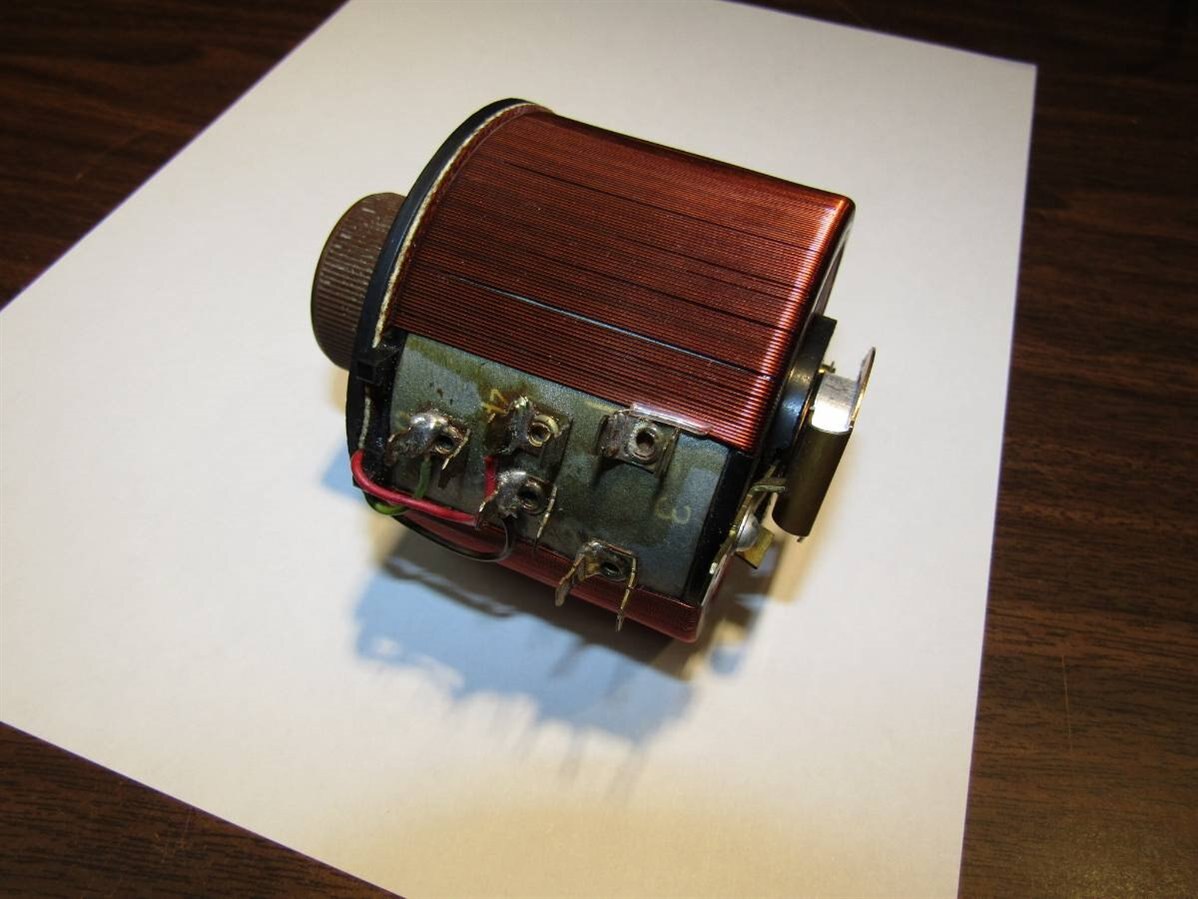
Besides the full 0 to 110 volt sweep contact this unit also had hard taps at 8, 17, and 55 volts. My plan is to rectify the 17 volt tap and use it to drive a 7812 regulator which in turn will provide the power for the fan in the gun. My test of the fan motor showed that it drew 0.25 Amps at 12 Volts and ran with enough RPM to serve my purpose. The 7812 can handle 1 amp when heat sunk so with a small radiator it should be able to dissipate the watt or so it will be required to shed.


It is not my intention to build a precision device but I do want to have some indication of what my input settings are so I can estimate the output temperature. Therefore an AC voltmeter will be used to monitor the voltage that is powering the heater element. I will combine the voltage with an empirical listing of approximate output temperatures on the dial of the variac to get my output temperature as close as practical to my target temperature. There are many variables that will contribute to the output temperature of the air. I have attempted to limit and control some of the variables such as the fan speed and the voltage to the element but ambient temperature will also be able to influence the output. I will be using a small 0 to 55 volt 4 digit 3 wire digital voltmeter module to display the AC volts.


image


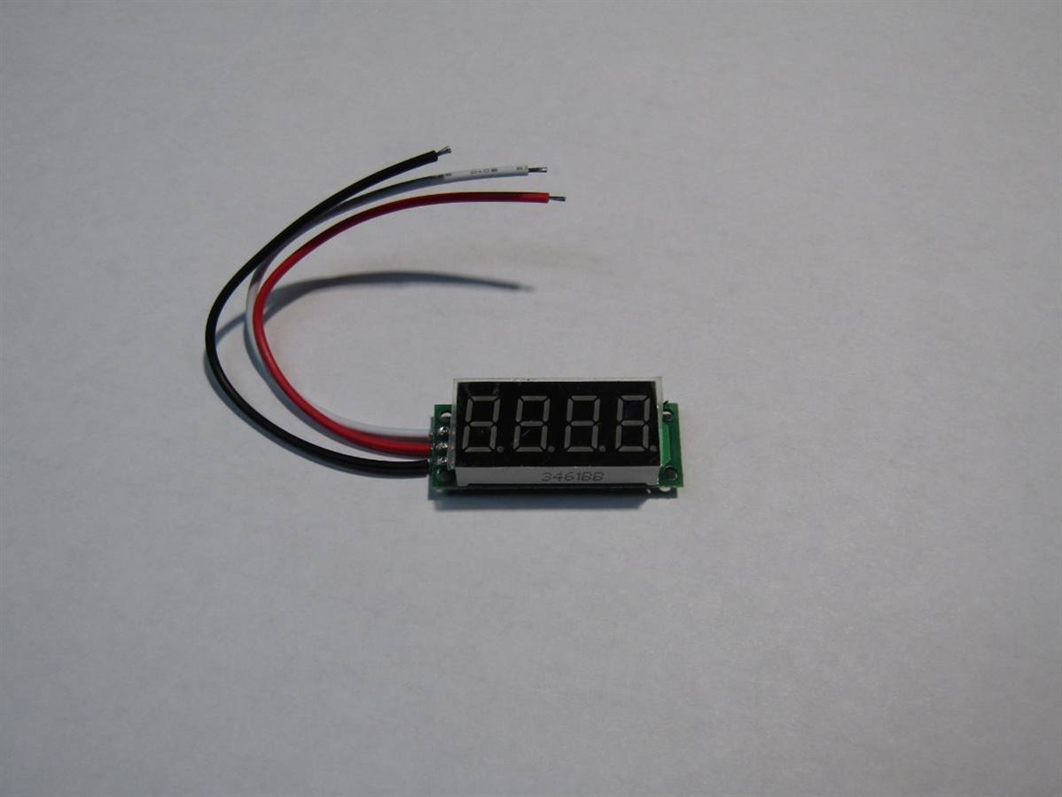
The challenges in using this module are that it is DC, doesn't read directly as high as I want to go, and requires an isolated power supply from the variac to do what I want it to do. I experimented with using the 8 volt and 17 volt taps on the variac to power it but I was not able to get it to zero. Finally I took an old linear 7 volt wall wart, broke it apart and used it to supply the power for the LEDs and logic. This allowed me to get accurate readings on the sense line. In the final design I used a 100K potentiometer as a voltage divider to to bring the voltage to the meter down one magnitude and then manually moved the decimal to properly reflect the real voltage. With a 4 digit display and no need for that much accuracy it left me with a good solution and the meter now displays 0 to 110 volts while actually sensing 0 to 11 volts.


Before I began the actual build I wanted to do some bench testing and to run some empirical measurements of current versus output temperature. For those who feel my bench is always too organized here is proof to the contrary.


image


image


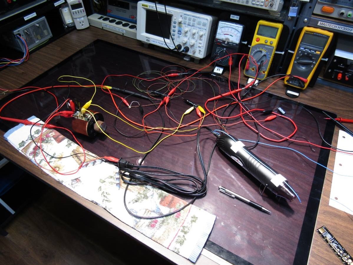
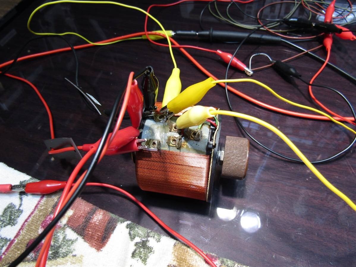
While I am working with some mains voltages in these tests I have taken special precautions to use isolated sources and good test procedures. Unfortunately sometimes there is just no way to make it look nice and get results in a reasonable time frame. Here is a graph of the Temperature versus Current characteristics of the heat gun. I have a very inexpensive two channel thermocouple based thermometer. I tested the thermocouple for accuracy using boiling water and ice in water. It actually tested extremely accurate considering it only cost $13.00. I placed one of the thermocouples 2 cm in front of the outlet of the heat gun and taped it in place. I wanted my readings to be consistent. Finally I fired the test up and took readings at 10 volt increments from 10 to 100 volts. I also used a second also inexpensive thermometer and you can see the difference between the black and red graph lines.


image


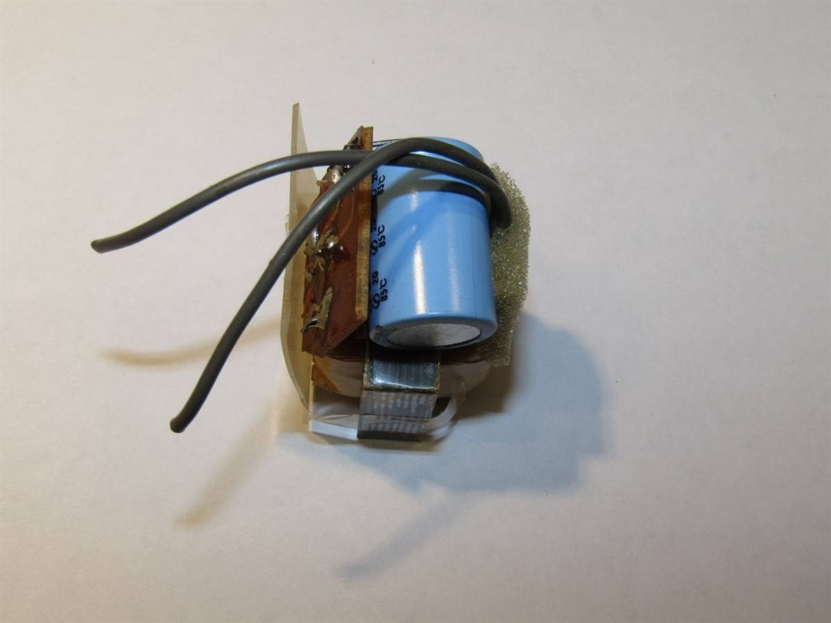
This will give me a rough estimate of my temperature output based on the voltage shown on the meter. Once I was convinced that things would work as envisioned I began the build. I had to make the small circuit for powering the fan motor and also one to adapt the AC voltage from the variac sweeper to what would be acceptable for the meter. The small isolated power supply for the meter's electronic was already built. Here is the motor board in progress.


image


and the salvaged wall wart:


image


Here is the schematic for the entire unit:


image

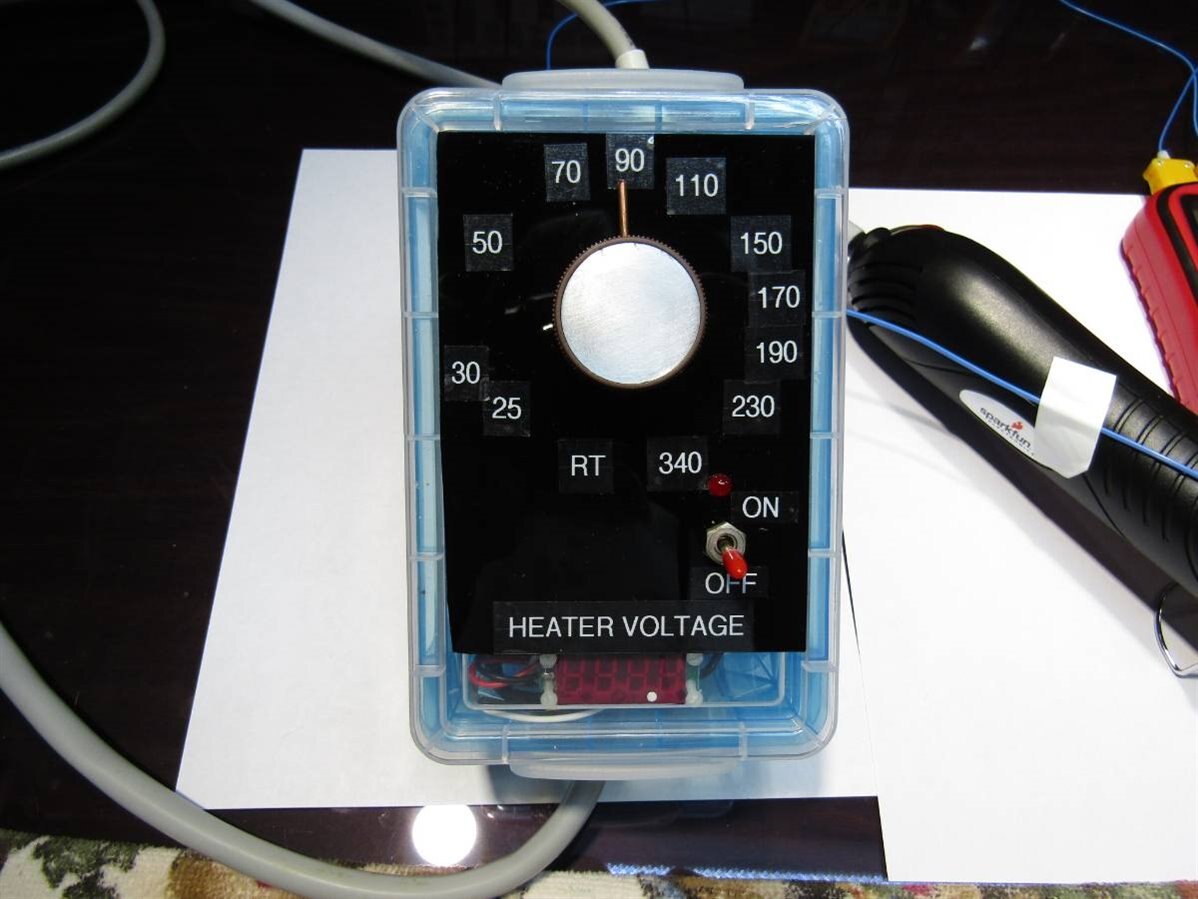
The construction preceded with the customary glitches. I had a bout of dyslexia and hooked the variac up backwards on the first test. I put way too much voltage on the fan motor for a split second and had to make a repair to the motor board. By the time I got things straightened out it was 3:30 AM. Once I knew it was working I went to bed and planned to put the finishing touches on it in the morning which begins about 10:00 AM for me. Here is the finished unit. The little thermocouple thermometer is still attached in the picture as I was running final tests and I wanted to place temperature labels on the face of the unit so I wouldn't have to use the graph to convert voltage to temperature. Here is the finished unit.


image


image


Finally I took a short video of how it works.


You don't have permission to edit metadata of this video.
Edit media
x
image
Upload Preview
image


John

  • Sign in to reply

Top Comments

  • jw0752
    jw0752 over 8 years ago +3
    I decided to use the new tool tonight to test a couple of components. The first one is a 100 K NTC Thermistor. I have begun taking data at 20 degrees C and continued at 10 degree steps until I reached…
  • jc2048
    jc2048 over 8 years ago in reply to jw0752 +3
    The transistor results are interesting. I don't remember giving you a permit to do transistor blogging, though. The relationship between hFE and temperature seems to be complicated. It depends on form…
  • jw0752
    jw0752 over 8 years ago in reply to jc2048 +2
    Hi Jon, The best part of my blogs are the insights from my mentors, like you, at the end of the blog. Thank you for taking the time to reply. Sorry I did not take data as the temperature came back down…
  • jw0752
    jw0752 over 8 years ago in reply to jc2048

    Hi Jon,

    The best part of my blogs are the insights from my mentors, like you, at the end of the blog. Thank you for taking the time to reply. Sorry I did not take data as the temperature came back down. You are correct it would have been informative. I did however, to answer Jan's request, take a reading when the transistor got back to room temperature and I was back to hfe of 311 and Vf of 677mV. Since the tester doesn't put any real load on the transistor I do not know if this means it wasn't damaged. Please continue your study and blogging on transistors as this foundational knowledge is so important to a good understanding of what is really going on and also the limitations of basic components. Thank you for the deputy's permit. image

    John

    • Cancel
    • Vote Up +2 Vote Down
    • Sign in to reply
    • More
    • Cancel
  • Jan Cumps
    Jan Cumps over 8 years ago in reply to jc2048

    Yes, that change at 160°C looks like junction damage.

    John, could you plug that same transistor back into the hFE meter, at any temperature, and see if the hFE is still within specs?

    • Cancel
    • Vote Up +1 Vote Down
    • Sign in to reply
    • More
    • Cancel
  • jc2048
    jc2048 over 8 years ago in reply to jw0752

    The transistor results are interesting. I don't remember giving you a permit to do transistor blogging, though.


    The relationship between hFE and temperature seems to be complicated. It depends on form of construction, doping type and density, and possibly other things. Normally it goes up with temperature. The 2N3904s I've been playing with have a much larger temperature dependence than you're looking at here, as you can see from this graph that I've taken from a Fairchild (now ON Semi) datasheet:


    image


    I'd have liked to have seen what happened as the temperature came down again - whether it traces the same curve back or the path is different. Is the lower hFE above 180 a permanent change?


    As to explaining the sharp rise at 150, my first guess - and this is pure speculation - would be that collector-base leakage, which I think doubles for every 10C rise, has risen to such a point that it is adding significantly to the base current coming from the tester which then can't show a true indication of the hFE. The peak at 170 would then be where you are damaging the device in some way and degrading the characteristics. But I could be wrong - I often am.


    The temperature dependence of hFE doesn't matter much - circuits have to be able to work with a very wide spread from device to device anyway. The variation of Vbe, in contrast, does matter, and a lot of the complication in transistor circuit design comes from dealing with it.


    PS Ignore my comment at the start - since you have a deputy's badge, I should probably be applying to you for a permit. 

    • Cancel
    • Vote Up +3 Vote Down
    • Sign in to reply
    • More
    • Cancel
  • jw0752
    jw0752 over 8 years ago

    I decided to use the new tool tonight to test a couple of components. The first one is a 100 K NTC Thermistor. I have begun taking data at 20 degrees C and continued at 10 degree steps until I reached 200 degrees
    C. Here is the graph for this experiment:


    image


    The second component is an MPS2907 NPN silicone transistor. I used a cheap dynamic transistor tester that returns Type, hfe, and Vf base to emitter with each test. Here again I began at 20 degrees C and continued at 10 degree intervals until I got to 200 degrees C. In case you are interested here is the data sheet for a MPS 2907.


    http://datasheet.octopart.com/MPS2907ARLRAG-ON-Semiconductor-datasheet-10126652.pdf


    image


    The data sheet shows the rated temperature range for this transistor is -55 degrees C to 150 degrees C. Just as predicted by the Data sheet strange things happened with the hfe as we went from 150 C to 160 C.


    image


    In this graph I have shown the change of the forward voltage drop base to emitter over the temperature range explored. Here again we see the drastic changes that occur once we get above recommended temperature. It was fun to be able to change the temperature slowly and be able to read instrumentation without the need to make quick readings. It was also nice to have reproducibility when needed.


    John

    • Cancel
    • Vote Up +3 Vote Down
    • Sign in to reply
    • More
    • Cancel
  • jw0752
    jw0752 over 8 years ago in reply to DAB

    Thanks DAB

    • Cancel
    • Vote Up 0 Vote Down
    • Sign in to reply
    • More
    • Cancel
>
element14 Community

element14 is the first online community specifically for engineers. Connect with your peers and get expert answers to your questions.

  • Members
  • Learn
  • Technologies
  • Challenges & Projects
  • Products
  • Store
  • About Us
  • Feedback & Support
  • FAQs
  • Terms of Use
  • Privacy Policy
  • Legal and Copyright Notices
  • Sitemap
  • Cookies

An Avnet Company © 2025 Premier Farnell Limited. All Rights Reserved.

Premier Farnell Ltd, registered in England and Wales (no 00876412), registered office: Farnell House, Forge Lane, Leeds LS12 2NE.

ICP 备案号 10220084.

Follow element14

  • X
  • Facebook
  • linkedin
  • YouTube