element14 Community
element14 Community
    Register Log In
  • Site
  • Search
  • Log In Register
  • Community Hub
    Community Hub
    • What's New on element14
    • Feedback and Support
    • Benefits of Membership
    • Personal Blogs
    • Members Area
    • Achievement Levels
  • Learn
    Learn
    • Ask an Expert
    • eBooks
    • element14 presents
    • Learning Center
    • Tech Spotlight
    • STEM Academy
    • Webinars, Training and Events
    • Learning Groups
  • Technologies
    Technologies
    • 3D Printing
    • FPGA
    • Industrial Automation
    • Internet of Things
    • Power & Energy
    • Sensors
    • Technology Groups
  • Challenges & Projects
    Challenges & Projects
    • Design Challenges
    • element14 presents Projects
    • Project14
    • Arduino Projects
    • Raspberry Pi Projects
    • Project Groups
  • Products
    Products
    • Arduino
    • Avnet & Tria Boards Community
    • Dev Tools
    • Manufacturers
    • Multicomp Pro
    • Product Groups
    • Raspberry Pi
    • RoadTests & Reviews
  • About Us
    About the element14 Community
  • Store
    Store
    • Visit Your Store
    • Choose another store...
      • Europe
      •  Austria (German)
      •  Belgium (Dutch, French)
      •  Bulgaria (Bulgarian)
      •  Czech Republic (Czech)
      •  Denmark (Danish)
      •  Estonia (Estonian)
      •  Finland (Finnish)
      •  France (French)
      •  Germany (German)
      •  Hungary (Hungarian)
      •  Ireland
      •  Israel
      •  Italy (Italian)
      •  Latvia (Latvian)
      •  
      •  Lithuania (Lithuanian)
      •  Netherlands (Dutch)
      •  Norway (Norwegian)
      •  Poland (Polish)
      •  Portugal (Portuguese)
      •  Romania (Romanian)
      •  Russia (Russian)
      •  Slovakia (Slovak)
      •  Slovenia (Slovenian)
      •  Spain (Spanish)
      •  Sweden (Swedish)
      •  Switzerland(German, French)
      •  Turkey (Turkish)
      •  United Kingdom
      • Asia Pacific
      •  Australia
      •  China
      •  Hong Kong
      •  India
      •  Japan
      •  Korea (Korean)
      •  Malaysia
      •  New Zealand
      •  Philippines
      •  Singapore
      •  Taiwan
      •  Thailand (Thai)
      •  Vietnam
      • Americas
      •  Brazil (Portuguese)
      •  Canada
      •  Mexico (Spanish)
      •  United States
      Can't find the country/region you're looking for? Visit our export site or find a local distributor.
  • Translate
  • Profile
  • Settings
Personal Blogs
  • Community Hub
  • More
Personal Blogs
John Wiltrout's Blog Unusual Way to Wire a small DC Motor
  • Blog
  • Documents
  • Mentions
  • Sub-Groups
  • Tags
  • More
  • Cancel
  • New
  • Share
  • More
  • Cancel
Group Actions
  • Group RSS
  • More
  • Cancel
Engagement
  • Author Author: jw0752
  • Date Created: 4 May 2017 11:12 PM Date Created
  • Views 1576 views
  • Likes 8 likes
  • Comments 14 comments
  • motor_circuits
Related
Recommended

Unusual Way to Wire a small DC Motor

jw0752
jw0752
4 May 2017

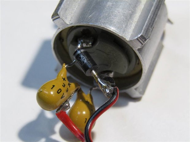
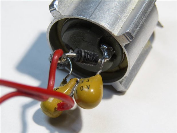
Despite 60 years of playing with electronics this is the first time I have seen a DC motor wired in this fashion.  At first I did not expect it to work on DC current but to my surprise it took off and ran perfectly. Furthermore it did not matter if the polarity was forward or reversed. The motor continued to spin happily along. Just for the fun I also applied an AC current and once again the motor continued to whirl away. Here are some pictures of the motor wiring:
 

image


image


image


image


Just to clarify how the motor is wired I also produced this small schematic:


image


On first appearances I assumed the motor would start to turn and then stop when the small tantalum capacitor became charged. I did not initially understand why this did not happen. I am hoping some of my friends on the Forum with more experience and knowledge will confirm my speculation that the counter EMF in the motor actually discharges the capacitor allowing it to accept a second charge and continue to maintain the magnetic fields that spin the motor. I suspect that the low ESR of the Tantalum caps makes their charge and discharge rapid enough to facilitate this process. I do not know why the designer of the piece of equipment where this small cooling fan was used chose to use this particular circuit. It was something new to me and it caught my attention. Now I just want to understand it.


John

  • Sign in to reply

Top Comments

  • jw0752
    jw0752 over 9 years ago +5
    One final observation. Using a Tantalum capacitor as I have done in these experiments does damage it and makes it unusable in a normal power application. To verify this I tested one of the 33 uF caps that…
  • jw0752
    jw0752 over 9 years ago +4
    SOLUTION FOUND! I took shabaz suggestion to try to set up the circuit using a different motor and other components. I was not able to get the motor to turn. I ran some tests on the original motor and found…
  • jw0752
    jw0752 over 9 years ago +4
    Tonight I will investigate whether the Tantalum capacitor has any characteristics related to temperature when it is hooked up in a circuit backward to normal polarity. I my previous post I was using the…
  • dougw
    dougw over 9 years ago

    Strange....

    How is this for speculation:

    Maybe if you think of the commutating motor as an inductor that is flipping back and forth between its terminals....initially current flows through the inductor to charge a capacitor.

    Wen it rotates it commutates which reverses the connection, but the current does not want to stop flowing through the inductor.

    This causes the side of the inductor that was receiving current to want more current and thus it goes low, discharging the capacitor that it is newly connected to.

    The exit side goes high to keep the current flowing, which charges the other capacitor - which could boost the high side voltage beyond the rail to start the next cycle.

    Maybe this is a way to limit motor current or motor speed with higher efficiency than using a resistor?

    It also seems to ensure the motor always turns in the same direction, regardless of voltage polarity, even AC, which is important for a fan.

    • Cancel
    • Vote Up +1 Vote Down
    • Sign in to reply
    • More
    • Cancel
  • shabaz
    shabaz over 9 years ago

    Interesting circuit! I too have never seen this. I'm tempted to try it on a motor, although it is late here. Sleepiness may override curiosity for once : )

    This is my guess, it could be wrong:


    Maybe it is worth picturing this like a bridge rectifier, i.e. diamond shape, with the two diodes at the top half of the bridge rectifier, and the two capacitors being the bottom half, and the motor therefore occupies the usual DC output position.

    When power is applied, (lets say +ve at the top, -ve at the bottom for now) then the right-most capacitor won't play any role in the voltage at the right side motor junction; the voltage will be high regardless of the charge state of that capacitor. On the left side, if we assume that the left capacitor is discharged then the motor gets a burst of power, enough to turn it. But, as it starts to turn, the current consumption drops because that left capacitor is charging. But, motor is spinning, and since the right side of the motor is held at a voltage, the back EMF causes the left side of the motor to drop to a very low voltage, to allow that left side capacitor to discharge. At some point the back EMF drops (due to slowed motor) which causes current to pass through the motor again, charging that left side capacitor again.

    Anyway, maybe I'm completely wrong : )

    • Cancel
    • Vote Up +3 Vote Down
    • Sign in to reply
    • More
    • Cancel
  • michaelwylie
    michaelwylie over 9 years ago in reply to kas.lewis

    DC motors can produce lots of noise themselves. I suspect the caps in the hobby RC application stop the wire motors from radiating interference, increasing the link range of the car.

    • Cancel
    • Vote Up +1 Vote Down
    • Sign in to reply
    • More
    • Cancel
  • kas.lewis
    kas.lewis over 9 years ago

    Hello John,


    I've seen this arrangement (without the diode) on hobby motors. More specifically I used to see it on RC car motors. I never fully understood why but just assumed the cap help[ed to remove noise or power ripples from the power lines.


    If someone else could explain this better I would love to have that understanding as well.


    Kas

    • Cancel
    • Vote Up +1 Vote Down
    • Sign in to reply
    • More
    • Cancel
<
element14 Community

element14 is the first online community specifically for engineers. Connect with your peers and get expert answers to your questions.

  • Members
  • Learn
  • Technologies
  • Challenges & Projects
  • Products
  • Store
  • About Us
  • Feedback & Support
  • FAQs
  • Terms of Use
  • Privacy Policy
  • Legal and Copyright Notices
  • Sitemap
  • Cookies

An Avnet Company © 2026 Premier Farnell Limited. All Rights Reserved.

Premier Farnell Ltd, registered in England and Wales (no 00876412), registered office: Farnell House, Forge Lane, Leeds LS12 2NE.

Follow element14

  • X
  • Facebook
  • linkedin
  • YouTube