Introduction
I’m working on test rig for accurately measuring the efficiency of DC-DC regulators or converters. It uses 2 precision current shunts to measure the input and output current. These need very low noise pre-amplifiers which must each be powered with an earth free floating +/-5V supply.
Standard bench PSUs are not ideal for this purpose, most have a fair amount of digital noise from the converter and/or the control system and don’t specify just how well they are isolated from common mode mains or ground. Dual rail tracking bench supplies are expensive, and those used with my test rig may be tied up for weeks.
The need for low power and low noise isolated supplies comes up quite often, so I decided to build my own. It turned out to be quite an interesting project and some of the design calculations and test results may be a little surprising.
The basic spec is +/- 5V output at 100mA maximum current, common 0V rail, isolated from ground (with low capacitance to ground).
Voltage tolerance +/- 5%.
Noise 10Hz-1MHz < 5mVpk-pk
Component Choices
I decided to use simple low cost linear regulators and chose the MC78M05BDTG and MCM7905BDTG parts which are readily available, cheap and conveniently packaged in what ON Semiconductor call DPAK-3.
These parts have internal current limit at 350mA, drop out voltage of 2V (7805, the 7905 is better) and ripple rejection of 54dB (7905) minimum.
The complete circuit looks like this:
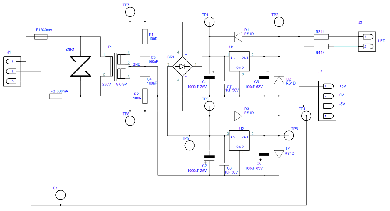
The mains supply (230V AC, no provision for other voltages) comes in via an IEC filter socket and a single pole switch in the live side. These connect in to J1.
Pin 3 of J1 is connected to the case of the filter socket and via screws to the aluminium enclosure.
Live and neutral are fused on the PCB by 630mA soldered in fuses. ZNR1 is a surge suppressor (Panansonic ERZE11A391, 250V max working voltage, 320V breakdown).
The transformer is a Block 2.3VA part with 9-0-9 secondary and rated as a safety isolating part. I really don’t want these supplies failing and damaging me or the test gear they are connected to.
The rest of the design is very straightforward using good quality capacitors. The caps across the unregulated supply are Wurth 10000 hours rated parts and would, at first sight, appear to be generously rated for voltage. (More on this later.)
Diodes D1 to D4 are referenced on the 7805 and 7905 data sheet but are usually omitted. They cost pennies and make the supply much more resistant to common fault conditions – so should be used for a general purpose supply.
R1,R2, C3 and C4 are there to reduce the noise from the bridge rectifier – I confess to not having measured the noise without them !
The bridge rectifier is a Diodes ABS10A-13 with a forward voltage drop at 1A of 1.1V.
The output is not connected to mains earth but mains earth may be accessed via connector J2 if required. My current design uses 3 pole output connectors so the mains earht is not available to them.
Calculations
Transformer output voltage
Block give this transformer (part number VB 2,3/2/9)a no load output voltage factor of 1.6 which is quite high.
Assuming mains input 230V +/- 10%
Max peak no load output voltage = (9 x 1.1 x 1.6 x 1.414) – 1.0 = 22.4 – 1.0 = 21.4 V
Min peak full load output voltage = 9 x 0.9 x 1.0 x 1.414 = 11.45 – 1.0 = 10.45 V
The lowest voltage into the regulator will be the min peak voltage – 100Hz ripple.
Ripple on C1 and C2
The ripple current is not sinusoidal and accurate calculations requires consideration of the impedances of transformer, rectifier and capacitors but a good approximation is to calculate the voltage drop on the capacitor for the maximum working current for 75% of the half cycle time.
For 50Hz supplies this is the voltage drop in 7.5ms. In this case the current is 100mA and capacitor is 1000uF so the voltage drop is 7.5E-3 x 0.1 / 1E-3 = 0.75V.
We can expect a ripple voltage at full load of about 0.75V pk-pk, which will result in a minimum voltage at the regulator inputs of 9.7V which leaves a respectable margin of 2.7V between the regulator drop out voltage and its input.
The ripple voltage at the output of the 7905 regulator should be less than 0.75 – 54dB = 1.5mV. The 7805 has higher ripple rejection and will do better.
The values of C5 and C6 have no simple direct effect on the output noise but will affect the transient response.
Safety Margins
C1 and C2 are rated at 25V and while the voltage across them will not exceed this with maximum mains in it will be very close. This will only happen at low loads so the capacitors will not be very hot.
If I were make any more of this supply I would use a capacitor with a higher voltage rating. Farnel stock some Vishay parts rated for 8000 hours 105C and 35V which would be a better choice (and will fit, being 5mm taller but otherwise the same size).
PCB Design
I used a 2 layer PCB 75mm square to fit in a Hammond box (1455k1201bk). This is one with a removable top which makes it much easier to fit the wires in.
The PCB has mains on it so I have made a big slot to reduce the chance of any leakage
This is the board with all its parts:
POPULATED BOARD
A completed power supply (without lid)
Test Results
DC
I made 5 of these supplies and the DC measurements look like this:
The supplies were powered from the mains via a Variac set for 240V but measured at approximately 252V AC. The voltage fluctuated a little (as much as 1%) during the tests.
|
|
no load |
100mA load |
||||||
|
|
unreg |
reg |
unreg |
reg |
||||
|
part |
+ |
- |
+ |
- |
+ |
- |
+ |
- |
|
1 |
20.0 |
19.8 |
5.003 |
4.962 |
12.1 |
12.0 |
5.005 |
4.963 |
|
2 |
19.7 |
19.6 |
5.011 |
4.926 |
11.6 |
11.5 |
5.012 |
4.929 |
|
3 |
19.9 |
19.7 |
5.008 |
4.954 |
11.9 |
11.8 |
5.009 |
4.955 |
|
4 |
19.9 |
19.7 |
5.006 |
4.938 |
12.0 |
11.9 |
5.007 |
4.940 |
|
5 |
20.0 |
19.8 |
5.010 |
4.949 |
12.0 |
11.9 |
5.011 |
4.949 |
The unregulated no load voltage was predicted at 21.4V for 253V and measured about 5% less. I suspect that the transformer regulation is a little better than Block claim.
The anticipated full load unregulated voltage was 10.45V and the actual measured voltage was about 1.5V higher. That’s a difference of about 14%.
The transformer works a bit better than claimed but the 5 samples tested were bought together and probably have a much tighter spread than would be expected over the full range of production and operating conditions.
There is certainly nothing alarming in the measurements .
The worst error in output voltage was only 1.24%.
Noise
I have been having trouble with measuring noise due to interference in a band around 60kHz. This turned out to be coming from the R&S MXO4 scope but not entirely its fault. I usually run it via an isolating mains transformer to avoid LF/DC earth loop faults – a thing I’ve done frequently with scopes and other instruments connected to high power loads ever since I blew up a nice Dell laptop by shorting a 1kW 50V DC power supply with a common earth with the Dell.
When I connect the MXO4 to mains via the isolating transformer I see a low level 60kHz noise on most measurements. I can get rid of it in the case of the little power supplies by connecting the MXO4 signal earth to the power supply case (mains earth). Or by using a common mains earth for the scope and power supply under test.
I tried using my Rigol DL Electronic Load but it generates some noise at about 5kHz so in the end all my noise tests were done with the MXO4 un-isolated and a 100R resistor from +5V to -5V for the load.
The initial measurements are only up to 1MHz so I used a 1M BNC <-> croc clip cable to connect the MXO4 to the PSU. The scope was set for AC coupling and used in high res mode with a 1MHz software filter and a 20MHz channel input filter. Later I slightly improved the scope to PSU connection for 20MHz measurements. The MXO4 can do spectral analysis and the usual kind of scope based measuring and statistics.
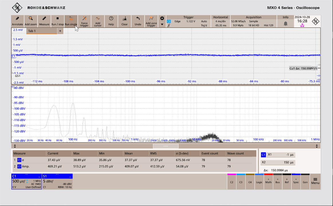
Noise on the positive rail
Noise on the negative rail
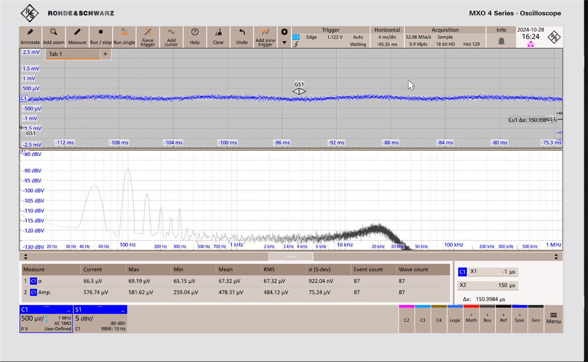
All 5 powers supplies had very similar noise results.
The 100Hz noise on the negative output is worse than that on the positive output (by about 6dB) and this shows in the measurement statistics window at the bottom of the screenshots.
The averages for the 5 PSUs were:
Pos pp-pk noise 425uV
Pos RMS noise 38.6uV
Neg pk-pk noise 495uV
Neg RMS noise 67uV
Comparing the noise with some Bench Power supplies
To put this in perspective,
the Keithley 2231A-30-3 (£832) offers 1mV RMS and 5mVpk-pk over 20Hz – 20MHz,
the Multicomp MP711002(£334) offers 2mV RMS over 20Hz to 20MHz,
the AIM-TTi EL302(£402) offers 1mV RMS 20MHz bandwidth.
The very fancy (and expensive) R&S power supplies (NGM and NGL ranges) offer lower noise (500uV 20MHz bandwidth).
Of course all these power supplies offer lots of features that my simple design does not but they all cost a lot more. I haven’t found a nice simple power supply from a reputable manufacturer.
1MHz or 20MHz bandwidth for noise measurements
All the bench power supplies specify noise up to 20MHz and for fairness I measured one of mine over the same range.
However – noise above 1MHz is not very important for the intended application of the simple PSU because any load it is connected to is likely to have its own filters. This is because the supply and load will be connected by a cable and low noise at the PSU end at 20MHz may not be that low at the other end unless expensive cables are used.
And sure enough – my measurements in the 20MHzbandwidth showed that under normal circumstances wires are as important as power supplies in the 20MHz band.
This is what I see with the power supply connected up to mains and scope but switched OFF:
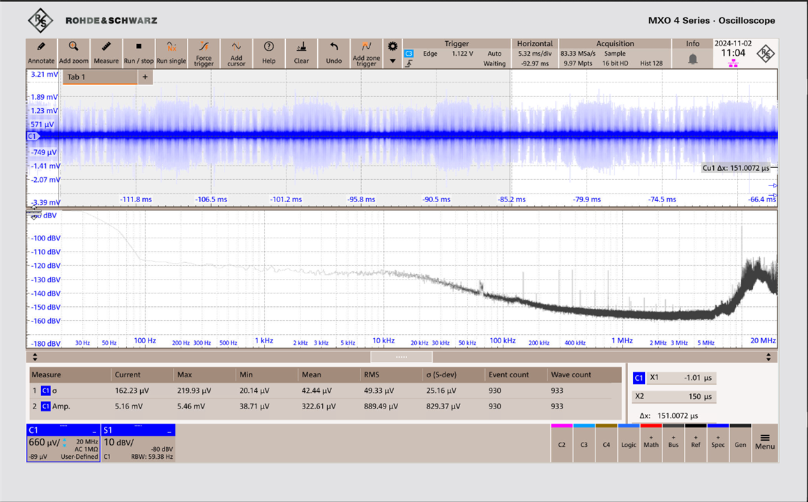
All that horrible HF fur (shown very clearly in the top scope trace) is making the measurements look horrible. But it can't come form the power supply because its not even turned on !
I added a big fat earth wire from the PSU case to the signal ground:
And the noise (supply off) is satisfactorily reduced:
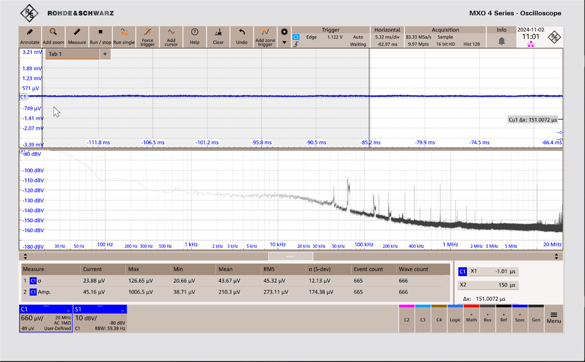
Although it could be influenced by moving the power supply about on the bench, the few inches of unscreened act as a reasonable aerial at 20MHz.
And with the supply switched on:
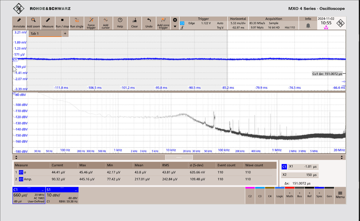
Even over the 20MHz bandwidth the dominant noise is the mains ripple.
The RMS noise over a 20MHz bandwidth is 45uV - way better than the bench supplies. With a bit more work it could be improved further because most of it is mains ripple and an improved PCB layout and/or bigger caps could solve that.
Isolation
The specifications of the bench supplies I have mentioned (except the MP711002) make it clear that the outputs are isolated from mains earth and most of them discuss the safe working floating voltages that may be applied. None of them specify the output to mains common mode capacitance !
My target spec for the isolated supply was that the capacitance should be low, and in fact it measures at 50pF. This is dominated by the internal capacitances of the mains transformer.
Summary
It’s not that hard to make a simple low noise mains driven dual power supply for powering analogue circuits, that is smaller, cheaper and quieter than typical bench supplies. It’s much less versatile but much better at doing its job.
My current design can be improved by the addition of a big earth tag for the box on the front panel (it does have provision for this in the connector but that won’t work as well for RF !)
The common practice of specifying power supply noise over a 20MHz bandwidth is not that helpful, separate figures for a lower bandwidth would be useful.
Measuring these very low signal levels at the higher frequencies requires a screened room for accurate results.

Top Comments
-

shabaz
-
Cancel
-
Vote Up
0
Vote Down
-
-
Sign in to reply
-
More
-
Cancel
-

Jan Cumps
in reply to shabaz
-
Cancel
-
Vote Up
0
Vote Down
-
-
Sign in to reply
-
More
-
Cancel
-

shabaz
in reply to Jan Cumps
-
Cancel
-
Vote Up
0
Vote Down
-
-
Sign in to reply
-
More
-
Cancel
Comment-

shabaz
in reply to Jan Cumps
-
Cancel
-
Vote Up
0
Vote Down
-
-
Sign in to reply
-
More
-
Cancel
Children