


Table of Contents
Introduction
Sean colporteur was recently looking for motor driver modules to replace older modules that had a few problems. The older modules were getting damaged. Part of the problem is that a lot of hobby motor driver boards employ the L298 integrated circuit, which is many decades old and does not offer built-in protection like modern circuits. Under certain scenarios, the L298 boards cannot be used without additional circuitry and still may not be suitable if the software or the connected motor or supplies or wiring are subject to change. For more information on those scenarios, see the following blog post and comments: Raising the Bridge...Automation with Arduino: Failure reconciliation
I had a look around, and the H450 module looked interesting; it is very low-cost and specified as suitable for 4.5-44V motors up to 2A. Each module can drive up to two normal DC motors (also known as permanent magnet DC motors or brushed DC motors) or one stepper motor. This blog post discusses how to use the modules to drive normal DC motors.

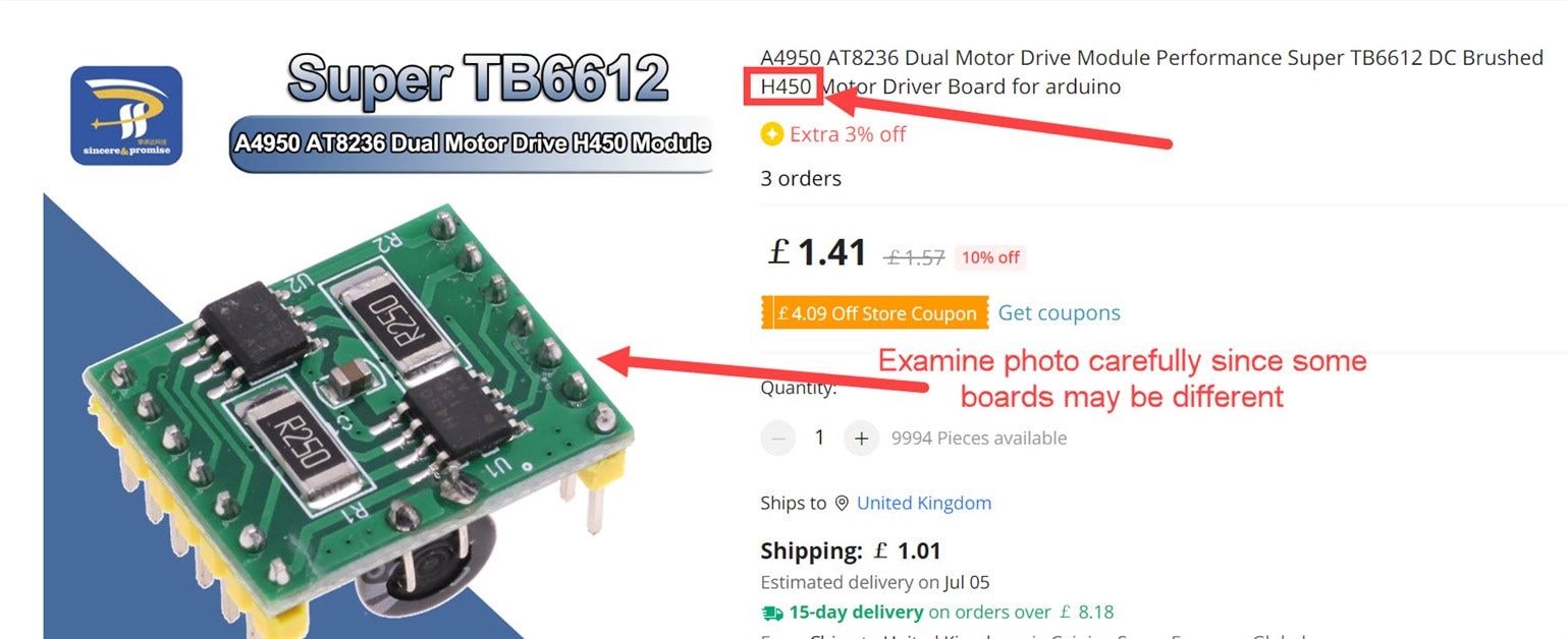
Note that the information here may also be compatible with A4950 boards too, but I don't know for sure. If you want to be entirely sure that the information here will help you, then carefully examine the photos further below in the blog post (in the Module Description section) and order an identical board (some may have subtle differences). The information here is also compatible with the DC Motor 6 Click Board as javagoza discusses in the comments below.
This blog post shows an Arduino board being used with the module, but it will work fine with the Pi Pico too (and any board with 3.3V or 5V logic, provided pins can be configured for PWM output, if speed control is desired).
Module Description
The module contains two Toshiba TB67H450FNG motor driver ICs. Each IC contains a single H-bridge circuit and logic/driver circuitry for it.

The board contains two of the chips and the bare minimum needed to use them:
The board has an electrolytic capacitor on the underside. If you’re not using pin sockets to plug the board, then the capacitor will need to be bent outwards. It’s a weird board design : )

The screenshot below shows the particular board that I used, although others might be compatible, I have not tried any others:
Motor Voltage (Power Source)
The module accepts a single 4.5 to 44V supply, labeled VM. The H-bridge will switch that voltage to the motors.
Motor Current Limit
There is a VREF pin, labeled VCC on the boards. That voltage must be 5V or lower. It determines the maximum current that the motors require. If the current demand goes higher, then the chip will switch off the H-bridge, protecting the motors and the chip itself.
The formula is: Imax = (VREF/10)/R where R is 0.25. This can be simplified to: Imax = VREF * 0.4. So, if VREF is set to 5V, then the maximum current is 2A. That’s the maximum value (VREF must not be set higher than 5V). If your motors only require 1A max, then VREF would be set to 2.5V.
The great thing about the current limit is that it can protect both the motor and the circuit, so it is worthwhile taking some time to find the best value, and a variable resistor can help, as discussed further below.
Using the Module
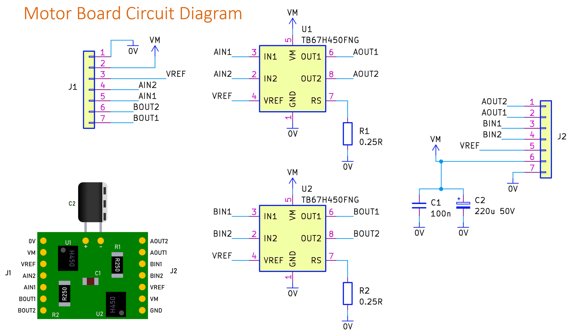
The circuit diagram below shows the minimal connections needed to use the board.

Note that it is a good idea to improve the circuit a little bit. The diagram below shows a more ideal circuit. Use an 18V Zener diode if the motor power supply is up to 12V, and it will provide a bit of protection from transient voltages caused by wire inductances. The suggested 18V Zener diode is 1N5355 .

This improved circuit uses a trimmer resistor to set the current limit per motor to between 0 and 2A. If you don’t need that and just want the maximum current, then the trimmer resistor is not needed, and the 1k resistor R1 can be wired to a 5V supply.
My constructed circuit is shown below; the only extra addition is a 78L05 voltage regulator circuit so that the 5V supply for the current setting trimmer resistor is generated locally from the motor power supply. It saves having to connect the 5V supply from the Arduino. The output from the 78L05 just goes to the trimmer resistor and nowhere else.

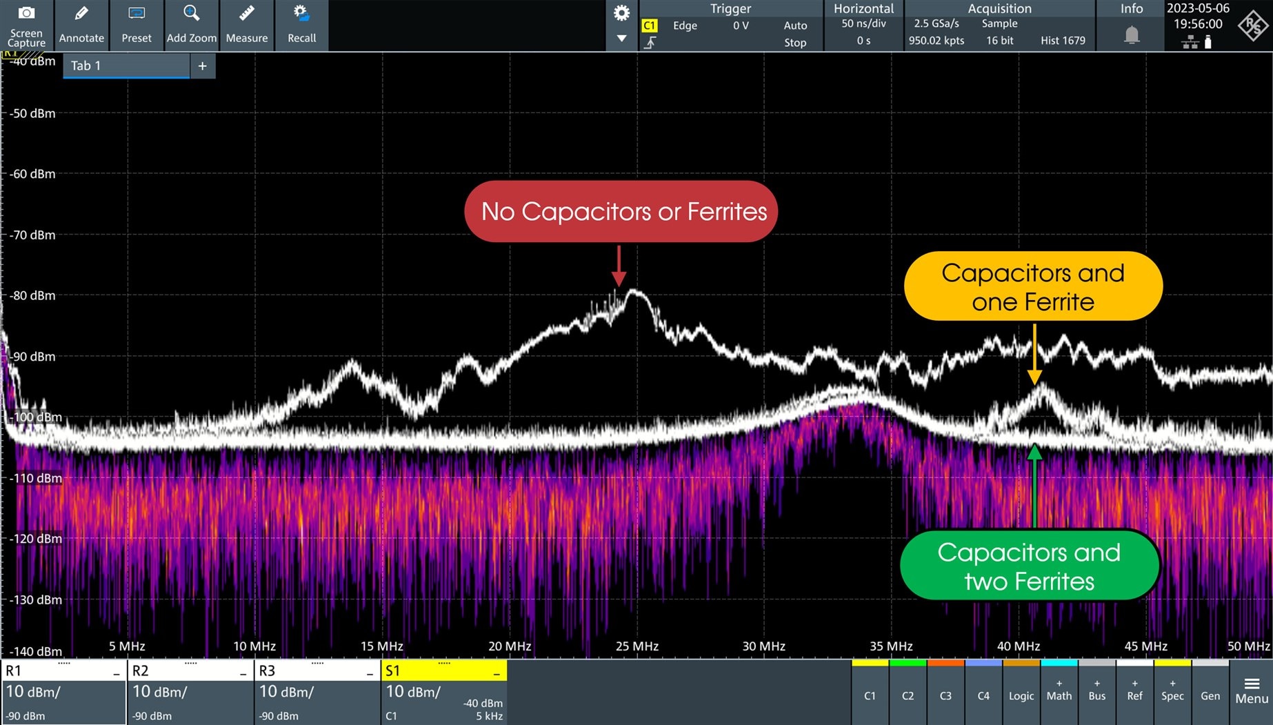
It is also good to be nice to radio users by placing a capacitor or two directly across each motor. Otherwise, users of wireless remote control circuits may experience limited range, and you won’t get great music reception on radios either, while using the circuit.
The suggested capacitors are 100nF and 10nF

It is also good to add a ferrite core to the motor wiring. You could either use a single ferrite core or one in each wire connected to the motor. Loop the wire through the ferrite several times. The photo above shows quite large ferrite cores because that was all I had. You could use smaller ones if you don’t have space, but the larger ones are usually more effective.
A suggested ferrite core is Fair-Rite 2631540202
A clip-on ferrite could be used too.
The DC to 50 MHz spectrum below shows that quite a noticeable improvement is made with the capacitors and ferrites.
Complete Circuit
The circuit diagram here shows a 78L05 voltage regulator added (it saves having to wire 5V from the Arduino or whichever microcontroller board is being used).
The circuit here has some 'Do Not Fit' components for flexibility. With R1 being a wire link, the current limit is set to 2A. R1 and R2 could be replaced with resistors if a different maximum current is needed.

The KiCad 7 project is on GitHub. Here is what the board looks like:

The 2-pin connectors for the motors and the power supply are screw terminals, and the holes are large enough to accept 3.5mm or 3.81mm pitch connectors for those. Alternatively, wires could be directly soldered.
The Gerber files are in a zip file called h450_motor_board_gerber_files.zip in that GitHub location.
Here is what the board may look like assembled:

I have not built this board, so there may be issues with it.
Software
Using the module with Arduino code is extremely easy. Firstly, make sure that the control pins (AIN1, AIN2, and [if you’re driving two motors] BIN1, BIN2) are connected to PWM-capable pins on whichever Arduino you are using, and make sure that the 0V (GND) connection is also made.
For my test, I connected just a single motor and used PWM pins 9 and 10.
The Arduino .ino file is available on GitHub.
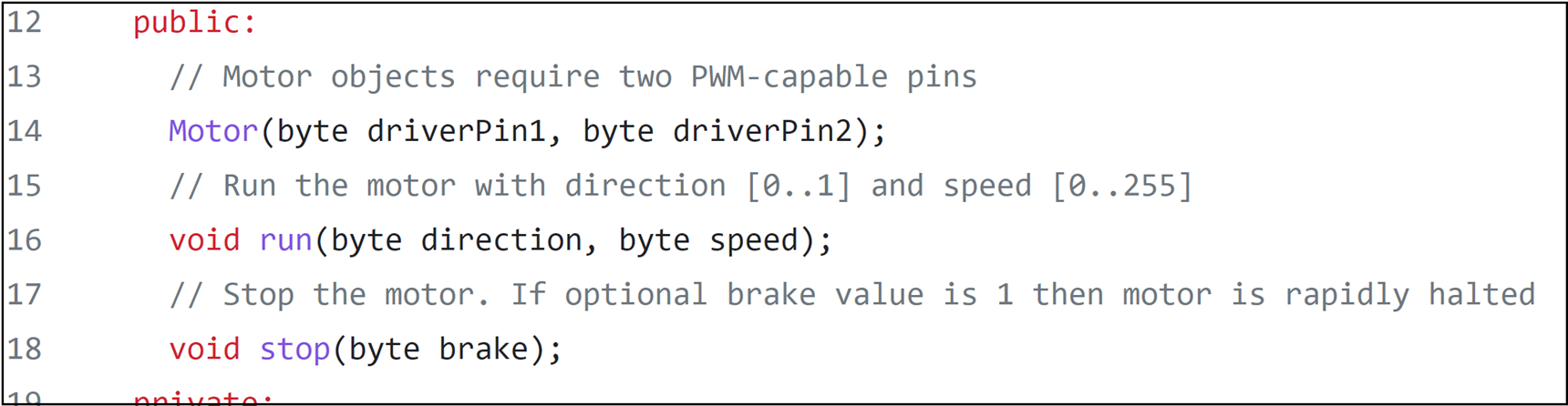
It is easy to follow along. Lines 5-59 contain the driver code, but you only need to examine just a handful of lines, lines 12-18 for the purposes of this blog post. Ordinarily, this code would be in a downloadable library, but since a lot of newcomers to C/C++ do not know how to create their own library, I thought it was worthwhile to keep this driver code in the main .ino file for now, so that they can see what goes inside a library. As can be seen, there’s not a lot of code!
Lines 12 to 18 describe the entire library; there are just three functions listed there! The first one is actually the “constructor” (this is C++ terminology) called Motor. It accepts two parameters, which are the pin numbers.
The only other two functions are called run and stop.
Here is how it would be used.
If a motor is connected to the PWM pins 9 and 10, then an instance of the Motor class is created by typing:
Motor mymotor(9,10);
To run the motor in a clockwise direction at a speed of 128 (the range is 0-255), type:
mymotor.run(DIR_CW, 128);
To run it in the other direction at top speed:
mymotor.run(DIR_CCW, 255);
To stop the motor:
mymotor.stop();
There’s a hard braking capability too, if that is desired:
mymotor.stop(HARD_BRAKE);
To use the motors with your own Arduino code, you could just copy-paste lines 5-59 into your .ino file and then make use of it, as shown in the example. Or you could just copy the entire example .ino file and edit it to suit your needs.
If you prefer an installable library (which is the correct way of doing things), that is an exercise for the reader. Hopefully, others can help with that if required (it is straightforward to do), but as mentioned, it is not essential, and it is a good learning exercise to be able to see the code for now.
Summary
The H450 modules are approximately just as cheap as L298 boards but the H450 ones are far better for motor control. This blog post describes how to make use of the boards, both in terms of hardware and software. I think they are very easy to use and are more likely to survive hardware and software issues.
If you have tried the H450 modules or any others, and have feedback, positive or negative, it would be great to hear.
Thanks for reading!
Top Comments