element14 Community
element14 Community
    Register Log In
  • Site
  • Search
  • Log In Register
  • Community Hub
    Community Hub
    • What's New on element14
    • Feedback and Support
    • Benefits of Membership
    • Personal Blogs
    • Members Area
    • Achievement Levels
  • Learn
    Learn
    • Ask an Expert
    • eBooks
    • element14 presents
    • Learning Center
    • Tech Spotlight
    • STEM Academy
    • Webinars, Training and Events
    • Learning Groups
  • Technologies
    Technologies
    • 3D Printing
    • FPGA
    • Industrial Automation
    • Internet of Things
    • Power & Energy
    • Sensors
    • Technology Groups
  • Challenges & Projects
    Challenges & Projects
    • Design Challenges
    • element14 presents Projects
    • Project14
    • Arduino Projects
    • Raspberry Pi Projects
    • Project Groups
  • Products
    Products
    • Arduino
    • Avnet Boards Community
    • Dev Tools
    • Manufacturers
    • Multicomp Pro
    • Product Groups
    • Raspberry Pi
    • RoadTests & Reviews
  • About Us
  • Store
    Store
    • Visit Your Store
    • Choose another store...
      • Europe
      •  Austria (German)
      •  Belgium (Dutch, French)
      •  Bulgaria (Bulgarian)
      •  Czech Republic (Czech)
      •  Denmark (Danish)
      •  Estonia (Estonian)
      •  Finland (Finnish)
      •  France (French)
      •  Germany (German)
      •  Hungary (Hungarian)
      •  Ireland
      •  Israel
      •  Italy (Italian)
      •  Latvia (Latvian)
      •  
      •  Lithuania (Lithuanian)
      •  Netherlands (Dutch)
      •  Norway (Norwegian)
      •  Poland (Polish)
      •  Portugal (Portuguese)
      •  Romania (Romanian)
      •  Russia (Russian)
      •  Slovakia (Slovak)
      •  Slovenia (Slovenian)
      •  Spain (Spanish)
      •  Sweden (Swedish)
      •  Switzerland(German, French)
      •  Turkey (Turkish)
      •  United Kingdom
      • Asia Pacific
      •  Australia
      •  China
      •  Hong Kong
      •  India
      •  Korea (Korean)
      •  Malaysia
      •  New Zealand
      •  Philippines
      •  Singapore
      •  Taiwan
      •  Thailand (Thai)
      • Americas
      •  Brazil (Portuguese)
      •  Canada
      •  Mexico (Spanish)
      •  United States
      Can't find the country/region you're looking for? Visit our export site or find a local distributor.
  • Translate
  • Profile
  • Settings
Arduino Tutorials
  • Products
  • Arduino
  • Arduino Tutorials
  • More
  • Cancel
Arduino Tutorials
Blog Getting to Know Arduino : Part 2 : Hello, Again!
  • Blog
  • Forum
  • Documents
  • Events
  • Polls
  • Files
  • Members
  • Mentions
  • Sub-Groups
  • Tags
  • More
  • Cancel
  • New
Join Arduino Tutorials to participate - click to join for free!
  • Share
  • More
  • Cancel
Group Actions
  • Group RSS
  • More
  • Cancel
Engagement
  • Author Author: cstanton
  • Date Created: 31 Mar 2014 9:06 AM Date Created
  • Views 2094 views
  • Likes 6 likes
  • Comments 1 comment
  • tutorial
  • min
  • 10
  • arduino uno
  • arduino-uno
  • ardunio
  • microcontrollers
  • 10minarduino
  • programming
  • atmega328
  • atmega328p
  • microcontroller
  • minute
  • 10minutearduino
  • uno
  • getting_to_know
  • getting to know
  • c++
  • arduino
  • feature tutorial
  • feature_tutorial
  • atmel
Related
Recommended

Getting to Know Arduino : Part 2 : Hello, Again!

cstanton
cstanton
31 Mar 2014

You don't have permission to edit metadata of this video.
Edit media
x
image
Upload Preview
image


Next Guide:

Getting to Know Arduino : Part 3 : Taking your Temperature


Previous Guide:

Getting to Know Arduino : Part 1 : Hello, World!


In part 1 of my Getting to Know Arduino, I blogged about flashing an LED (light emitting diode) with the Arduino UnoArduino Uno and how to get started with it using an A to B USB cableA to B USB cable. However, we only flashed the LED that was on the circuit board of the Arduino and we didn't actually get to building any circuitry with it, but in the blog post we did look into the code behind the flashing of the LED.


Now, what we can do is the same again, only this time, a little differently. You will need the following, or a variant there of:


  • BreadboardBreadboard
  • WiresWires
  • LEDsLEDs
  • ResistorsResistors (of appropriate rating of resistance measured in ohms)


Along with the Arduino IDE installed onto your computer. When you have your parts, you will want to plug them into your breadboard and there is a specific way to plug them in to complete the circuit.


The Arduino's input/output (IO) pin sockets is where we then connect from digital pin 13 (D13) through a resistor to the LED to ground (GND). It is important to have a resistor in the circuit to prevent damage to your LED, some Arduino boards have an on board resistor in series with the IO header for pin 13 but it is safer not to take that risk else you'll let the magic blue smoke out and your LED will become an FED (fire emitting diode).


If you're unsure as to what resistor to use, you could take the unorthodox approach of using the highest value resistor you can find and scaling down until you find the right one, or you can calculate it. If you're uncomfortable with this, typically a 1Kohm resistor will do, but I often cheat and use an online calculator, if you do not use an online calculator then you will want to use Ohms Law to work it out. Once you've read the specifications of your LED and you know the forward voltage (or just voltage) and the forward current (or just current) in mA (milliamperes) and the source voltage (you can find out from the specifications on the Arduino, but I can easily tell you it is 5volts) then you can work out the required resistor.


It is important to get used to being aware of the requirements of the components and not just LEDs you're using and what resistors are required.


Here is an example of a completed setup:


image


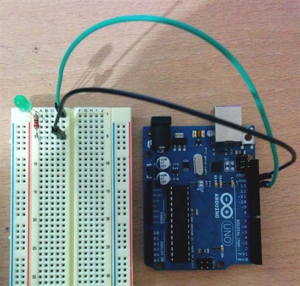
On a typical breadboard there is a grid referencing system. As you can partly see in the photograph it is labelled A to J along the columns across the top and numbered from 1 downwards for the rows.


Here we connect our LEDs positive pin to the digital IO pin socket (from row 2 on the breadboard to pin 13 on the Arduino) while we then connect a resistor (row 1 on the breadboard to row 5) and ground (GND from the Arduino to row 5 on the breadboard).


It is also worth to note that the LED is 'keyed' as to its orientation from positive to negative (or anode/cathode). Typically the shorter leg on the LED which also has a flat side to the plastic casing is the negative/ground/cathode side.


It has been known that cheap LEDs you can acquire have been manufactured incorrectly and that the casing on the LED has been rotated. So sometimes it is a lucky dip as to whether or not it will turn into a FED depending on the build quality.

Now you can connect your Arduino up to the computer and upload the example Blink program, if you still have the Blink example program uploaded to your Arduino then we will see that the LED will blink in unison with the on board LED 'L'.


Equally if we connect the LED to pins 1 or 0 on the Arduino, we would see it blink in unison when there is data sent to/from the Arduino.


Since you've now got an external LED connected to the Arduino, you can try connecting a few of them in line with one another, in series. Or, you can alter your sketch so that it will blink an LED from more than just the one pin depending on what variable values you use.


Have a go and experiment, if you have any problems then please leave a comment. There's also the element14 The specified item was not found. community group!

  • Sign in to reply
  • jc2048
    jc2048 over 9 years ago

    Good blog. Explaining how to connect a circuit is a nice step on from watching an LED on a board blink.


    I hope it's all right if I comment on one or two things you wrote - don't think of it as criticism, think of it as me adding to and refining what you've done:-


    "typically a 1Kohm resistor will do"


    The photograph has a 220 ohm resistor.

    Doesn't really matter. Either would do, they just result in different currents, but it might be a bit confusing for a beginner who isn't very sure about reading resistor colour codes.


    "...the forward current (or just current) in mA (milliamperes)..."


    If using Ohm's Law, calculate with the current in amps, not milliamps. So if you want 10mA, use 0.01A in the equation.


    For example, if the forward voltage of your LED were 2V, then for 10mA the resistor would be


    R = V / I


    R = (5V - 2V) / 0.01 = 300 ohms.


    The voltage in the equation is 3V, and not 2V, because it's the voltage across the resistor we are interested in, not the voltage across the LED (and the voltage across the resistor is what's left after the LED has had 2V from the 5V that's on offer).


    "It has been known that cheap LEDs you can acquire have been manufactured incorrectly and that the casing on the LED has been rotated. So sometimes it is a lucky dip as to whether or not it will turn into a FED depending on the build quality."


    That's a bit unfair to the manufacturers. There never was a correct way. In the early days you used to see both; it's just that, later on, manufacturers started choosing the one that got a lead in the market and it's ended up with mostly one orientation with just an odd few the other way.


    If you have the resistor in place, it's unlikely you'll damage the LED by putting it in the wrong way round. If the LED has an anti-static protection diode, the resistor will limit the current enough not to blow it up [don't run it for too long like that, though], and if there isn't a protection diode, the LED will normally survive a reverse voltage of 5V [datasheets often used to give 5V as the minimum absolute max reverse breakdown voltage, but in practice it would be higher than that because they give themselves a safe margin]. Just remember not to connect it without the resistor.


    "... and the source voltage (you can find out from the specifications on the Arduino, but I can easily tell you it is 5volts)..."


    Look up the Atmel datasheet for the ATMega328 and refer to the graph on page 356 (Figure 30-71). There you'll see that with a supply voltage of 5V, the output pin will sit down to 4.45V if you sink 20mA from it (at 25C).

    • Cancel
    • Vote Up 0 Vote Down
    • Sign in to reply
    • More
    • Cancel
element14 Community

element14 is the first online community specifically for engineers. Connect with your peers and get expert answers to your questions.

  • Members
  • Learn
  • Technologies
  • Challenges & Projects
  • Products
  • Store
  • About Us
  • Feedback & Support
  • FAQs
  • Terms of Use
  • Privacy Policy
  • Legal and Copyright Notices
  • Sitemap
  • Cookies

An Avnet Company © 2025 Premier Farnell Limited. All Rights Reserved.

Premier Farnell Ltd, registered in England and Wales (no 00876412), registered office: Farnell House, Forge Lane, Leeds LS12 2NE.

ICP 备案号 10220084.

Follow element14

  • X
  • Facebook
  • linkedin
  • YouTube