element14 Community
element14 Community
    Register Log In
  • Site
  • Search
  • Log In Register
  • Community Hub
    Community Hub
    • What's New on element14
    • Feedback and Support
    • Benefits of Membership
    • Personal Blogs
    • Members Area
    • Achievement Levels
  • Learn
    Learn
    • Ask an Expert
    • eBooks
    • element14 presents
    • Learning Center
    • Tech Spotlight
    • STEM Academy
    • Webinars, Training and Events
    • Learning Groups
  • Technologies
    Technologies
    • 3D Printing
    • FPGA
    • Industrial Automation
    • Internet of Things
    • Power & Energy
    • Sensors
    • Technology Groups
  • Challenges & Projects
    Challenges & Projects
    • Design Challenges
    • element14 presents Projects
    • Project14
    • Arduino Projects
    • Raspberry Pi Projects
    • Project Groups
  • Products
    Products
    • Arduino
    • Avnet Boards Community
    • Dev Tools
    • Manufacturers
    • Multicomp Pro
    • Product Groups
    • Raspberry Pi
    • RoadTests & Reviews
  • Store
    Store
    • Visit Your Store
    • Choose another store...
      • Europe
      •  Austria (German)
      •  Belgium (Dutch, French)
      •  Bulgaria (Bulgarian)
      •  Czech Republic (Czech)
      •  Denmark (Danish)
      •  Estonia (Estonian)
      •  Finland (Finnish)
      •  France (French)
      •  Germany (German)
      •  Hungary (Hungarian)
      •  Ireland
      •  Israel
      •  Italy (Italian)
      •  Latvia (Latvian)
      •  
      •  Lithuania (Lithuanian)
      •  Netherlands (Dutch)
      •  Norway (Norwegian)
      •  Poland (Polish)
      •  Portugal (Portuguese)
      •  Romania (Romanian)
      •  Russia (Russian)
      •  Slovakia (Slovak)
      •  Slovenia (Slovenian)
      •  Spain (Spanish)
      •  Sweden (Swedish)
      •  Switzerland(German, French)
      •  Turkey (Turkish)
      •  United Kingdom
      • Asia Pacific
      •  Australia
      •  China
      •  Hong Kong
      •  India
      •  Korea (Korean)
      •  Malaysia
      •  New Zealand
      •  Philippines
      •  Singapore
      •  Taiwan
      •  Thailand (Thai)
      • Americas
      •  Brazil (Portuguese)
      •  Canada
      •  Mexico (Spanish)
      •  United States
      Can't find the country/region you're looking for? Visit our export site or find a local distributor.
  • Translate
  • Profile
  • Settings
Arduino
  • Products
  • More
Arduino
Blog What would be your bare minimum on a Nano project PCB?
  • Blog
  • Forum
  • Documents
  • Quiz
  • Events
  • Polls
  • Files
  • Members
  • Mentions
  • Sub-Groups
  • Tags
  • More
  • Cancel
  • New
Join Arduino to participate - click to join for free!
  • Share
  • More
  • Cancel
Group Actions
  • Group RSS
  • More
  • Cancel
Engagement
  • Author Author: colporteur
  • Date Created: 8 May 2023 8:29 PM Date Created
  • Views 1685 views
  • Likes 14 likes
  • Comments 12 comments
  • arduino_development
  • arduino
Related
Recommended

What would be your bare minimum on a Nano project PCB?

colporteur
colporteur
8 May 2023

image

I’ve purchased the Arduino Nano holders above in the past for projects.

image

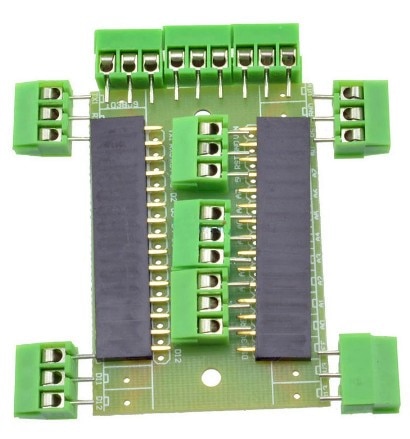
I have gone one step further and created PCB’s to hold a Nano and a JQ6500 sound module. I can share the KiCAD files if someone is interested. I reluctant to post them until I can improve the quality.

The ellipses shown on the boards proves that just because you can find a KiCAD footprints doesn't mean it is right. The ellipses on the left shows bow-legged pins because the footprint was wider than the actual module. The foot print dimension for the ellipse on the right were also off by 2.54mm. Live and learn.

After baring witness to Shabaz PCB design, I thought what would the E14 Community put as the bare minimum on a project board. I agree "it depends on what you want to do on the board." But I'm thinking there would be some general support even before the project starts. Things like power, protection, options.......

In the above project example. There is power I/P. I included a diode to prevent computer power feeding back into the power supply. I'm thinking maybe a 5V power supply. My design has the JQ6500 being supplied by the Nano. The example above uses 12VDC I/P. The 5V PS used in Shabaz design would be great on this board. Note my design doesn't have any filter capacitors that are see on other PCB's.

I'm currently working on a single Nano multi-function animation PCB. The board would have option to support light, sound and motion. The light would be LED's, the sound is the JQ6500 module and the motion would be some type of motor control. I'm currently thinking 5V servo but that is expanding. The board above supports a MOSFET module to drive a 12V load. There is a input to trigger the Nano with a button and speaker pins. 

I'm trying to get the model railroad community I play in, interested in microcontroller animation. If there was a small inexpensive PCB that allowed them to dabble in Arduino code to create simple animations, Lights coming on in a building. a car horn honking or a door opening on a building (i.e. light, sound and motion) maybe it would generate some interest. 

I'm curious what are your bare minimums for a Arduino project type board?

  • Sign in to reply
  • Andrew J
    Andrew J over 2 years ago in reply to shabaz

    Well, there you go.  I'd have thought it would have complained but I've gone and checked: the part is just defined as a graphic circle 1.27mm in radius.  There is a Mounting Hole with Pad component as well which does require a connection.

    • Cancel
    • Vote Up 0 Vote Down
    • Sign in to reply
    • More
    • Cancel
  • shabaz
    shabaz over 2 years ago in reply to Andrew J

    Hi Andrew,

    I've never checked the Gerber files to see what KiCad does with the circles, I just assumed that it might not be recorded as a drill (since there is a list of drill diameters that get recorded in the Gerber files). Probably the software (either KiCad, or the manufacturer's CAM software) is intelligent enough to realize. It's to give the manufacturer the option to either choose to use a drill (if it is a diameter for which they have such a drill) or to use a milling bit. Maybe it's anachronistic and not essential.

    Regarding errors, none are generated (it is OK with no connection). There are different mounting hole footprints, some with a connection, and some that are bare holes. They just appear like this in the schematic:

    image

    • Cancel
    • Vote Up 0 Vote Down
    • Sign in to reply
    • More
    • Cancel
  • colporteur
    colporteur over 2 years ago in reply to Andrew J

    IC mounts are a useful idea.

    I've suffered the enclosure dilemma myself and still struggle to get it right.

    I've ran across bad vendor footprints. I've have to develop a confirmation process if I go in search of a footprint or build my own as you folks are doing.

    • Cancel
    • Vote Up 0 Vote Down
    • Sign in to reply
    • More
    • Cancel
  • Andrew J
    Andrew J over 2 years ago in reply to shabaz

    Shabaz, I’ve only ever used edge cuts for mounting holes as I’ve never even considered it would be done any other way!  Why do you think the mfr would prefer them as footprints?  Do you not get ECR flags on the schematic for these holes when added as parts due to a lack of connection (perhaps they are all grounded?)

    • Cancel
    • Vote Up 0 Vote Down
    • Sign in to reply
    • More
    • Cancel
  • Andrew J
    Andrew J over 2 years ago

    I don’t think I have any minimum for Arduino boards but then again, I’ve only used UNO or Mega boards so far and had them as separate elements in an enclosure, wired to a PCB.  I would use IC mounts for any IC rather than two rows of headers as the spacing will be correct.

    The toughest thing I’ve come across is selecting an enclosure because the filters on sales sites are never quite good enough: if I have an intention to enclose a project, I now find it way better to find the enclosure (aesthetically pleasing) and then design the PCB around that choice as it’s always seemed a lot more difficult the other way around.  This is especially so if you have board mounted switches, button, dials etc. that must be presented through an enclosure panel.

    Having been burnt more than once on Kicad library footprints, I’ve learnt to double-check them against a datasheet or create my own.  Even common, innocuous components can have dodgy footprints.

    • Cancel
    • Vote Up 0 Vote Down
    • Sign in to reply
    • More
    • Cancel
>
element14 Community

element14 is the first online community specifically for engineers. Connect with your peers and get expert answers to your questions.

  • Members
  • Learn
  • Technologies
  • Challenges & Projects
  • Products
  • Store
  • About Us
  • Feedback & Support
  • FAQs
  • Terms of Use
  • Privacy Policy
  • Legal and Copyright Notices
  • Sitemap
  • Cookies

An Avnet Company © 2025 Premier Farnell Limited. All Rights Reserved.

Premier Farnell Ltd, registered in England and Wales (no 00876412), registered office: Farnell House, Forge Lane, Leeds LS12 2NE.

ICP 备案号 10220084.

Follow element14

  • X
  • Facebook
  • linkedin
  • YouTube