element14 Community
element14 Community
    Register Log In
  • Site
  • Search
  • Log In Register
  • About Us
  • Community Hub
    Community Hub
    • What's New on element14
    • Feedback and Support
    • Benefits of Membership
    • Personal Blogs
    • Members Area
    • Achievement Levels
  • Learn
    Learn
    • Ask an Expert
    • eBooks
    • element14 presents
    • Learning Center
    • Tech Spotlight
    • STEM Academy
    • Webinars, Training and Events
    • Learning Groups
  • Technologies
    Technologies
    • 3D Printing
    • FPGA
    • Industrial Automation
    • Internet of Things
    • Power & Energy
    • Sensors
    • Technology Groups
  • Challenges & Projects
    Challenges & Projects
    • Design Challenges
    • element14 presents Projects
    • Project14
    • Arduino Projects
    • Raspberry Pi Projects
    • Project Groups
  • Products
    Products
    • Arduino
    • Avnet Boards Community
    • Dev Tools
    • Manufacturers
    • Multicomp Pro
    • Product Groups
    • Raspberry Pi
    • RoadTests & Reviews
  • Store
    Store
    • Visit Your Store
    • Choose another store...
      • Europe
      •  Austria (German)
      •  Belgium (Dutch, French)
      •  Bulgaria (Bulgarian)
      •  Czech Republic (Czech)
      •  Denmark (Danish)
      •  Estonia (Estonian)
      •  Finland (Finnish)
      •  France (French)
      •  Germany (German)
      •  Hungary (Hungarian)
      •  Ireland
      •  Israel
      •  Italy (Italian)
      •  Latvia (Latvian)
      •  
      •  Lithuania (Lithuanian)
      •  Netherlands (Dutch)
      •  Norway (Norwegian)
      •  Poland (Polish)
      •  Portugal (Portuguese)
      •  Romania (Romanian)
      •  Russia (Russian)
      •  Slovakia (Slovak)
      •  Slovenia (Slovenian)
      •  Spain (Spanish)
      •  Sweden (Swedish)
      •  Switzerland(German, French)
      •  Turkey (Turkish)
      •  United Kingdom
      • Asia Pacific
      •  Australia
      •  China
      •  Hong Kong
      •  India
      •  Korea (Korean)
      •  Malaysia
      •  New Zealand
      •  Philippines
      •  Singapore
      •  Taiwan
      •  Thailand (Thai)
      • Americas
      •  Brazil (Portuguese)
      •  Canada
      •  Mexico (Spanish)
      •  United States
      Can't find the country/region you're looking for? Visit our export site or find a local distributor.
  • Translate
  • Profile
  • Settings
Arduino
  • Products
  • More
Arduino
Arduino Forum Different result if connecting 9V?
  • Blog
  • Forum
  • Documents
  • Quiz
  • Events
  • Polls
  • Files
  • Members
  • Mentions
  • Sub-Groups
  • Tags
  • More
  • Cancel
  • New
Join Arduino to participate - click to join for free!
Actions
  • Share
  • More
  • Cancel
Forum Thread Details
  • Replies 15 replies
  • Subscribers 395 subscribers
  • Views 1453 views
  • Users 0 members are here
  • tmp 36
  • problem
  • power supply
  • arduino
  • sensor
Related

Different result if connecting 9V?

Former Member
Former Member over 9 years ago

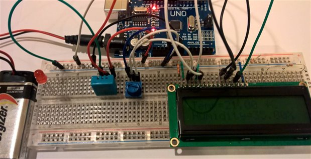
I have done the project in Jeremy Blum "Explorign Arduino" related to the three color LED changing with the temperature. It works right when connected with USB, but it is always red if connected to 9V.

Did I do anything wrong? is it normal? how can I solve it?

The sensor is a TMP-36image

  • Sign in to reply
  • Cancel

Top Replies

  • clem57
    clem57 over 9 years ago +1
    To learn, you need to read the datasheet on the sensor and think what changes with the switch from USB to 9 volt battery. Clem
  • Former Member
    Former Member over 9 years ago +1
    Per John's comment, I'm assuming you're using a 9V barrel adapter. A couple of points: 1. You have to get enough power for the Arduino, the LED, the TMP36, etc. I never use carbon-zinc batteries or cells…
  • clem57
    clem57 over 9 years ago in reply to Former Member +1
    Sensors are very dependant on the voltage provided. Change the voltage, they need to be recalibrated. Try a separate independent power source on the rail to the sensor that is 5V. repeat the experiment…
  • clem57
    clem57 over 9 years ago

    To learn, you need to read the datasheet on the sensor and think what changes with the switch from USB to 9 volt battery.

    Clem

    • Cancel
    • Vote Up +1 Vote Down
    • Sign in to reply
    • Cancel
  • jw0752
    jw0752 over 9 years ago

    Hi Jose,

    Where are you attaching the 9 volts?

    John

    • Cancel
    • Vote Up 0 Vote Down
    • Sign in to reply
    • Cancel
  • Former Member
    Former Member over 9 years ago

    Per John's comment, I'm assuming you're using a 9V barrel adapter.

    A couple of points:

    1.     You have to get enough power for the Arduino, the LED, the TMP36, etc.  I never use carbon-zinc batteries or cells (usually labeled "Heavy-Duty").  I prefer Lithium batteries or cells as they can output high current, when needed; but alkaline batteries/cells should be OK.  Check the battery: not just the voltage, but how much current it can output.  Preferably use a new battery.

    2.     The type of problem you're seeing is almost always due to insufficient power.

    3.     Since it's working properly with USB power (original USB 2.0 specifies 5V at 500mA) that should tell you what you need to replicate for total max power.

    • Cancel
    • Vote Up +1 Vote Down
    • Sign in to reply
    • Cancel
  • jw0752
    jw0752 over 9 years ago in reply to Former Member

    Hi Brian,

    I have also found that even with batteries it is usually a good idea to have a decoupling capacitor across the power feed.

    John

    • Cancel
    • Vote Up 0 Vote Down
    • Sign in to reply
    • Cancel
  • jw0752
    jw0752 over 9 years ago

    Hi Jose,

    Your hookup looks good. As Brian has pointed out there is no reason why it will not work if the power source is solid and hooked to the DC input jack or to the Ground and Vin terminals of the Arduino header. I would also put a 0.1 uF cap across the 9 Volts near the Arduino. That book by Jeremy is excellent and I had a lot of fun working through it a while back.

    John

    • Cancel
    • Vote Up 0 Vote Down
    • Sign in to reply
    • Cancel
  • Former Member
    Former Member over 9 years ago in reply to jw0752

    Thank you for the answer. I have checked with another board with a LCD and a DTH 11 sensor and the difference is 2 degrees centigrade between USB and 9v. What I can't understand is why. I thought the board provided 5v when connected to either 9V or USB.  I have checked the battery and it is providing 6.54v.


    imageimage

    • Cancel
    • Vote Up 0 Vote Down
    • Sign in to reply
    • Cancel
  • clem57
    clem57 over 9 years ago in reply to Former Member

    Sensors are very dependant on the voltage provided. Change the voltage, they need to be recalibrated. Try a separate independent power source on the rail to the sensor that is 5V. repeat the experiment and report back the results.

    Clem

    • Cancel
    • Vote Up +1 Vote Down
    • Sign in to reply
    • Cancel
  • mcb1
    mcb1 over 9 years ago in reply to clem57

    I think you'll find that the 5v line is less than 5v while being powered from USB.


    Clem is correct that it will need recalibrating.

    I tend to always use a Dallas One Wire DS18B20 (or similar) to avoid this.


    Mark

    • Cancel
    • Vote Up 0 Vote Down
    • Sign in to reply
    • Cancel
  • michaelkellett
    michaelkellett over 9 years ago in reply to Former Member

    Do you have a reasonably accurate DMM - if so try measuring some voltages around you circuit and you will be able to work out what is changing and affecting the result - it might then be simple to deal with the problem. If you post the circuit you have I can suggest places to measure.


    MK

    • Cancel
    • Vote Up 0 Vote Down
    • Sign in to reply
    • Cancel
  • jc2048
    jc2048 over 9 years ago

    The TMP36 output is 10mV per degree C and is designed to be 750mV at 25C.


    The sensor is specced for -40 to +125, which means a voltage range at the output of 0.1V to 1.75V. That range is designed to allow operation off of a low voltage supply like 3.3V or less, but it does mean that in this case you are only using about a third of the A/Ds range.


    I'm not really familiar with the Uno, but it looks like the A/D is 10-bit and is operating ratiometrically [taking the supply as its reference voltage]. Let's try calculating the reading for 25 degrees C (ie an input of 0.75V) for two different supply voltages [I've just arbitrarily chosen plus or minus 4% from a nominal 5V]


    supply 5.2V, reading 148  (0.75 / 5.2V) * 1024
    supply 4.8V, reading 160  (0.75 / 4.8V) * 1024


    Each step from the A/D is equivalent to approximately 1/2 a degree, so that [quite modest] change in the supply constitutes about 6 degrees C in the calculated temperature. Since you are seeing about 2 degrees, it means your supply change is less than that.


    Point is, the design is very sensitive to the supply voltage.


    If you want it to work accurately regardless of the supply voltage then there are several options:


    1) use the internal 1.1V reference of the ATMEGA328. That will be accurate and won't vary with the supply voltage. Limits you to 60 degrees C if you connect the sensor directly. You could get the full range if you use a potential divider on the sensor output.


    2) provide your own reference and set the processor to use that rather than the supply. A 2.5V reference into AREF would be appropriate. [It might be that the Uno software would conflict with having an external reference, so have a look around and see if this is generally done or not. If you are still not sure, put a resistor between the reference output and the AREF pin so that you don't have two outputs driving each other directly and look at the voltages either end to see if there is any difference before your own code runs and sets up the processor to use the external reference.]


    3) A final alternative would be to amplify the output from the sensor so that it makes better use of the A/D's input range. The effect of any supply change would then decrease in proportion. So if you amplified it 3 times, the effect from the supply change would be a third. If you don't need the full -40 to +125 degree range, you could amplify it even more with just the range you were interested in giving a full 0 to +5V at the A/D pin.


    All would require you to change the way the software calculates the temperature from the result- so only try it if you are confident programming, though I'm sure you'd get a lot of help from people here if you wanted to give it a go.


    And the TMP36 could do with a decoupling capacitor across its supply pins.

    • Cancel
    • Vote Up +1 Vote Down
    • Sign in to reply
    • Cancel
>
element14 Community

element14 is the first online community specifically for engineers. Connect with your peers and get expert answers to your questions.

  • Members
  • Learn
  • Technologies
  • Challenges & Projects
  • Products
  • Store
  • About Us
  • Feedback & Support
  • FAQs
  • Terms of Use
  • Privacy Policy
  • Legal and Copyright Notices
  • Sitemap
  • Cookies

An Avnet Company © 2025 Premier Farnell Limited. All Rights Reserved.

Premier Farnell Ltd, registered in England and Wales (no 00876412), registered office: Farnell House, Forge Lane, Leeds LS12 2NE.

ICP 备案号 10220084.

Follow element14

  • X
  • Facebook
  • linkedin
  • YouTube