element14 Community
element14 Community
    Register Log In
  • Site
  • Search
  • Log In Register
  • About Us
  • Community Hub
    Community Hub
    • What's New on element14
    • Feedback and Support
    • Benefits of Membership
    • Personal Blogs
    • Members Area
    • Achievement Levels
  • Learn
    Learn
    • Ask an Expert
    • eBooks
    • element14 presents
    • Learning Center
    • Tech Spotlight
    • STEM Academy
    • Webinars, Training and Events
    • Learning Groups
  • Technologies
    Technologies
    • 3D Printing
    • FPGA
    • Industrial Automation
    • Internet of Things
    • Power & Energy
    • Sensors
    • Technology Groups
  • Challenges & Projects
    Challenges & Projects
    • Design Challenges
    • element14 presents Projects
    • Project14
    • Arduino Projects
    • Raspberry Pi Projects
    • Project Groups
  • Products
    Products
    • Arduino
    • Avnet Boards Community
    • Dev Tools
    • Manufacturers
    • Multicomp Pro
    • Product Groups
    • Raspberry Pi
    • RoadTests & Reviews
  • Store
    Store
    • Visit Your Store
    • Choose another store...
      • Europe
      •  Austria (German)
      •  Belgium (Dutch, French)
      •  Bulgaria (Bulgarian)
      •  Czech Republic (Czech)
      •  Denmark (Danish)
      •  Estonia (Estonian)
      •  Finland (Finnish)
      •  France (French)
      •  Germany (German)
      •  Hungary (Hungarian)
      •  Ireland
      •  Israel
      •  Italy (Italian)
      •  Latvia (Latvian)
      •  
      •  Lithuania (Lithuanian)
      •  Netherlands (Dutch)
      •  Norway (Norwegian)
      •  Poland (Polish)
      •  Portugal (Portuguese)
      •  Romania (Romanian)
      •  Russia (Russian)
      •  Slovakia (Slovak)
      •  Slovenia (Slovenian)
      •  Spain (Spanish)
      •  Sweden (Swedish)
      •  Switzerland(German, French)
      •  Turkey (Turkish)
      •  United Kingdom
      • Asia Pacific
      •  Australia
      •  China
      •  Hong Kong
      •  India
      •  Korea (Korean)
      •  Malaysia
      •  New Zealand
      •  Philippines
      •  Singapore
      •  Taiwan
      •  Thailand (Thai)
      • Americas
      •  Brazil (Portuguese)
      •  Canada
      •  Mexico (Spanish)
      •  United States
      Can't find the country/region you're looking for? Visit our export site or find a local distributor.
  • Translate
  • Profile
  • Settings
Arduino
  • Products
  • More
Arduino
Arduino Forum can i talk to multiple arduinos at the same time with another arduino, in a serial format?
  • Blog
  • Forum
  • Documents
  • Quiz
  • Events
  • Polls
  • Files
  • Members
  • Mentions
  • Sub-Groups
  • Tags
  • More
  • Cancel
  • New
Join Arduino to participate - click to join for free!
Actions
  • Share
  • More
  • Cancel
Forum Thread Details
  • State Verified Answer
  • Replies 28 replies
  • Answers 3 answers
  • Subscribers 395 subscribers
  • Views 2834 views
  • Users 0 members are here
Related

can i talk to multiple arduinos at the same time with another arduino, in a serial format?

Former Member
Former Member over 10 years ago

Hello all,


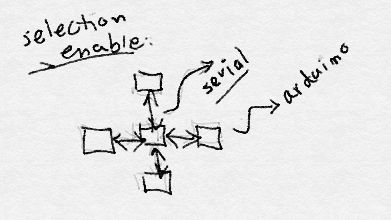
I am trying to talk to multiple (say 4) microcontrollers (Arduinos) at the same time. I was wondering if i can setup a serial connection, with a selection line that can detect the neighbor Arduino and enable the corresponding pin to start the serial communication between the two. something like this:image

  • Sign in to reply
  • Cancel

Top Replies

  • bobcroft
    bobcroft over 10 years ago +2 suggested
    Karim, further to Peter's reply I have done something similar to what you want to do using RS485 modules bought cheaply from China / Hong Kong. (Have a look on www.yourduino.com for modules and very useful…
  • Robert Peter Oakes
    Robert Peter Oakes over 10 years ago +1 verified
    There are several options and without complex switching, the standard TTL pins on D0 and D1 are off the table, at least for direct use I2C is an option, each arduino would have its own address assigned…
  • Former Member
    Former Member over 10 years ago in reply to Robert Peter Oakes +1 suggested
    it is quite of a simple concept: you have multiple units that you can mix and match to pave the way for an assistive surface for tactile sensing, which is modular. so the units may be added/removed from…
  • Former Member
    0 Former Member over 10 years ago in reply to Robert Peter Oakes

    it is quite of a simple concept: you have multiple units that you can mix and match to pave the way for an assistive surface for tactile sensing, which is modular. so the units may be added/removed from the swarm or replaced with another one, with no difference in the performance of the system. as a result each unit (node) consists of a microcontroller that processes the sensors' input, and transfers those values, along with its own ID, to the one directly connected, and ultimately to a base unit. I am hoping this clarifies...hence the sensors are needed, as well as all 6 serial communication with other units. would it be possible for me to make 6 soft serials out of the pins of Arduino Micro? 6 RX, 6 TX, 1 VCC and 1 GND?

    • Cancel
    • Vote Up +1 Vote Down
    • Sign in to reply
    • Verify Answer
    • Reject Answer
    • Cancel
  • balearicdynamics
    0 balearicdynamics over 10 years ago in reply to Robert Peter Oakes

    Peter,

    your suggestion has sense but. image

    If the nodes should be absolutely distributed on more than few arduino units as we are thinking, I suppose that in this biomedical application there is somethng like the need of a contemporary needs for reading. So the fact that some sensors will work without Arduino it is true but in the meantime I can't see how the sensor data can be processed - near simultaneously - if there is not a microcontroller. If a single Arduino board should dialogate with other six in the meantime the delays can be considered meaningless with the I2C bus interconnecting the units. But still a delay exist.

    In a grid like the one decised by karimkarim if every board has a small fixed number of board to dialogate with, it is replicated at least for every central node board. So the small delay of a single board, expands in a topography of this king creating a meaningful delay when there are more "six groups nodes" connected together. There are two possible changes that I will adopt in if I were Karim:


    The first is to change the topology to reduce the hierarchy of the boards, adding more cross connections to the board. If every Arduino is connected with all the proximity boards there are more links per board but with a resulting global faster distribution of the data flow as the number of effective delays are reduced; take a look to the modified topology scheme in the following image:

    Adding few more links (the dashed lines) to the original topology designed by Karim (the straight lines) the paths are drastically reduced and the average delay to send a generic data package between two board is reduced too. For example, a data packet sent from the board A2 to the board D1 in the original topology should follow the pathimage


    [A2] -> [A] -> [B] -> [C] -> [D] -> [D1]


    While including the dashed connections to the grid it can be reduced to


    [A2] -> [A1] -> [D1]


    This kind of topology has also the advantage to offer in most cases different paths for the same extreme points with the following advantages:


    1. If the immediately next board when needed has the bus busy (is working with another board) the path can be dynamically changed starting from that node.
    2. There is a more balanced distribution of the data charge between nodes.

    For example supposing that in the second example, when the data packet arrives from [A2] (starting point) to [A1] (better next node). The next better node to reach [D2] is [D1]. If it is busy, instead of waiting for the bus freed the destination point [D2] can also be reached with the alternative (longer) path [B] -> [C] -> [D] -> [D2]

    This kind of nodes communication is similar to the node distribution strategies of the network and the algorithm to find the next better node from every node is not difficult to calculate (we should think that these are microcontrollers).


    The second not less important thing that I will change is to adopt the ChipKit alternative with a board faster (80MHz instead of the max 20 of the arduino) with a similar price and a reduced number of boards needed. This last suggestions is just to improve the global speed and performance but maybe it is not needed, we have no idea of what should be really done by Karim.


    Enrico

    • Cancel
    • Vote Up 0 Vote Down
    • Sign in to reply
    • Verify Answer
    • Cancel
  • michaelkellett
    0 michaelkellett over 10 years ago in reply to Former Member

    Almost certainly the best way (cheapest and easiest) to implement this network is with a single RS485 link connecting all the devices together. This will allow you to use the hardware UART on the Arduino.

    One of the devices needs to be a master but all the bus information is available to any connected device.

    I don't think any standard protocol will work that well so you will need to invent your own.

    If we do the sums for 32 nodes it looks like this:


    115200 baud communications, 32 nodes, = approx 360 bytes per second per node, let's assume that we due to switching overheads and timing guard bands we only get  256 bytes/ per mode per second, so if each message is 8 bytes long you could have 32 messages per node per second - if one byte of the message is ID and another is a check sum  you get 6 bytes of data per message - if this isn't enough you can increase the baud rate to 250000 but you will have problems if you try to go much faster.


    Roughly the way the protocol would work is that the master would send out a synch message every 'frame' time (about 32 times per second in this example) and the slaves would each transmit their own little packet of data at their allotted time (which they could calculate from knowing their address) - this way only one slave ever talks at a time, each slave only needs to listen for a short time when it expects the frame synch message from the master (or at other times too if it wants more data.) So each slave only needs 2 interrupts per frame time - or 64 per second which will be a much lower software overhead than trying to run 6 software UARTS.


    You'll need to spend quite a lot of time working on the protocol to get it right but you can re-assure yourself that it is viable in principle since a similar scheme is used with supermarket shelf edge labels (using very low power radio links not wire) in systems with thousands of nodes. One of the issues you need to resolve is network discovery - when you switch the system on the master needs to work out how many nodes are attached and what their addresses are.


    I don't know why you are using an Arduino for this - it totally not the ideal processor - you would be far better off using an ARM Cortex based chip which would give you much more processing power for similar cost.


    MK

    • Cancel
    • Vote Up +1 Vote Down
    • Sign in to reply
    • Verify Answer
    • Cancel
  • Former Member
    0 Former Member over 10 years ago in reply to michaelkellett

    Thank you Michael,

    Unfortunately the conditions I explained above should stay intact.

    As a result, there is very little I can do with modifying the problem itself, instead need to solve it straight, as it is.

    One thing I thought was worth mentioning is that the processing of the sensor data is not a big deal. The Arduino only needs to take the analog sensor data, and at the max, convert it to digital form. So then it only needs to have its ID, its MAC, and sensor data ready at its serial ports...

    A few milli seconds of delay (even if more, as the delay is propagated) is not an issue, and of course the distance is zero between every two units.

    Karim.

    • Cancel
    • Vote Up 0 Vote Down
    • Sign in to reply
    • Verify Answer
    • Cancel
  • shabaz
    0 shabaz over 10 years ago

    One unique microcontroller (made by XMOS) has a built-in fabric using something called xConnect - it can be used to create a mesh of devices for fairly high speed transfers. Very cool.

    Not only that, but you can call functions residing on other microcontrollers using this scheme. That's something that transputers could do as well, and the technology made its way into

    today's XMOS devices. It's all a digression, but nevertheless they are very interesting microcontrollers for mesh functionality.


    Anyway, just to add to the possible topologies since star/bus/mesh have been discussed, yet another option for typical microcontrollers (I implemented on some old PICs in assembler

    a long time ago - I don't have code to share, sorry!) is to create a chain of devices, i.e. there are left and right interfaces at each microcontroller, i.e. a 1-dimensional mesh.

    At the end of the chain, the wire(s) are left unconnected. Think of train carriages.


    With some imaginative (i.e. non-standard) protocol you can push short (few bytes) messages (and retrieve the response or responses) across the entire chain, and auto detect the end

    of the chain since there will be no response. You can also detect position (i.e. ordering), if you give each device an identifier.

    It has its limitations, and could be a (relatively) slow method, but depending on the scenario might be good enough for short time-insensitive messages for a small quantity of

    devices - my scenario needed response times suitable for human-to-machine interaction for short message transfer for up to several dozen nodes (i.e. more than the six nodes quantity that you mentioned),

    and it was fine for that.

    You'd need to design the protocol (I cannot share mine), but it's not hard.


    Also, I wouldn't use an AVR or low-end PIC for this today either unless there was a compelling reason.

    • Cancel
    • Vote Up 0 Vote Down
    • Sign in to reply
    • Verify Answer
    • Cancel
  • Former Member
    0 Former Member over 10 years ago in reply to shabaz

    Thank you Shabaz,

    As I mentioned, I need to have mesh network with any unit being able to talk to (at max) 4 to 6 other units. So a chain topology is out of perspective. There was an image I shared, which I am attaching to this post for your attention. Having said all this, and I am assuming you have kindly had a look at the discussion, could you be more specific about the XMOS devices? Also, could you, at all, comment on the soft serial? By a low-end PIC do you mean an Arduino? I appreciate you being more precise.

    Karim.image

    • Cancel
    • Vote Up 0 Vote Down
    • Sign in to reply
    • Verify Answer
    • Cancel
  • michaelkellett
    0 michaelkellett over 10 years ago in reply to Former Member

    I don't see how the solution I suggested doesn't meet the requirements - each node can have several pairs of signal contact for connecting to other nodes - all that is needed is that all the nodes connect in parallel to the same pair of data lines.

    Any node can talk to any number of other nodes.

    You should be able to get this to work with Atmel AVR processors like you find in Arduinos since it only needs one UART and one timer per node and the processing burden is way less than you could hope for with multiple soft UARTS.

    If you need to establish the position in the mesh of each node automatically you will need additional connections on each side of each node but these would not need to operate all the time or fast.


    I'm not clear as how big the mesh might be - what is the maxim size it can grow to ?


    MK

    • Cancel
    • Vote Up 0 Vote Down
    • Sign in to reply
    • Verify Answer
    • Cancel
  • Former Member
    0 Former Member over 10 years ago in reply to michaelkellett

    well may be I am misunderstanding your point. but what you are suggesting is a main bus line with units connected to it. However if i may give a more complete diagram of the problem, here it is:

    image

    now please consider the fact that this system is a mesh, not a bus,not just a star.

    • Cancel
    • Vote Up 0 Vote Down
    • Sign in to reply
    • Verify Answer
    • Cancel
  • michaelkellett
    0 michaelkellett over 10 years ago in reply to Former Member

    You are confusing the the physical topology with the logical topology.

    My suggestion is that the devices are physically connected in parallel (not star !!!) and they can be logically connected any way you like (depends on protocol.)

    But you still need to say how many nodes you might need (parallel connection has a limit on the maximum). A physical mesh network has no physical limit to the number of nodes but will run n into issues with the time taken for data to propagate through it and the volume of data running through "pinch" points in the mesh.


    Mesh networks can work well when most data transfer is between devices which are close together. If most of the data goes from nodes to base unit then the mesh network performs worse than the parallel bus connection - the data flow is limited by the speed of a single link but the processing overhead is much greater.


    MK

    • Cancel
    • Vote Up +1 Vote Down
    • Sign in to reply
    • Verify Answer
    • Cancel
  • Former Member
    0 Former Member over 10 years ago in reply to michaelkellett

    Michael, the number of serial connections is a max. of 6.

    However, as part of the requirement, a unit may communicate with the base unit directly or indirectly through another unit. the physical and logical topology are congruent, in the case of this project. but why is this a confusing point? true! I mentioned star as the topology I was suggesting. Could you, however, draw a rough sketch to show the point more clearly?

    • Cancel
    • Vote Up 0 Vote Down
    • Sign in to reply
    • Verify Answer
    • Cancel
<>
element14 Community

element14 is the first online community specifically for engineers. Connect with your peers and get expert answers to your questions.

  • Members
  • Learn
  • Technologies
  • Challenges & Projects
  • Products
  • Store
  • About Us
  • Feedback & Support
  • FAQs
  • Terms of Use
  • Privacy Policy
  • Legal and Copyright Notices
  • Sitemap
  • Cookies

An Avnet Company © 2025 Premier Farnell Limited. All Rights Reserved.

Premier Farnell Ltd, registered in England and Wales (no 00876412), registered office: Farnell House, Forge Lane, Leeds LS12 2NE.

ICP 备案号 10220084.

Follow element14

  • X
  • Facebook
  • linkedin
  • YouTube