element14 Community
element14 Community
    Register Log In
  • Site
  • Search
  • Log In Register
  • About Us
  • Community Hub
    Community Hub
    • What's New on element14
    • Feedback and Support
    • Benefits of Membership
    • Personal Blogs
    • Members Area
    • Achievement Levels
  • Learn
    Learn
    • Ask an Expert
    • eBooks
    • element14 presents
    • Learning Center
    • Tech Spotlight
    • STEM Academy
    • Webinars, Training and Events
    • Learning Groups
  • Technologies
    Technologies
    • 3D Printing
    • FPGA
    • Industrial Automation
    • Internet of Things
    • Power & Energy
    • Sensors
    • Technology Groups
  • Challenges & Projects
    Challenges & Projects
    • Design Challenges
    • element14 presents Projects
    • Project14
    • Arduino Projects
    • Raspberry Pi Projects
    • Project Groups
  • Products
    Products
    • Arduino
    • Avnet Boards Community
    • Dev Tools
    • Manufacturers
    • Multicomp Pro
    • Product Groups
    • Raspberry Pi
    • RoadTests & Reviews
  • Store
    Store
    • Visit Your Store
    • Choose another store...
      • Europe
      •  Austria (German)
      •  Belgium (Dutch, French)
      •  Bulgaria (Bulgarian)
      •  Czech Republic (Czech)
      •  Denmark (Danish)
      •  Estonia (Estonian)
      •  Finland (Finnish)
      •  France (French)
      •  Germany (German)
      •  Hungary (Hungarian)
      •  Ireland
      •  Israel
      •  Italy (Italian)
      •  Latvia (Latvian)
      •  
      •  Lithuania (Lithuanian)
      •  Netherlands (Dutch)
      •  Norway (Norwegian)
      •  Poland (Polish)
      •  Portugal (Portuguese)
      •  Romania (Romanian)
      •  Russia (Russian)
      •  Slovakia (Slovak)
      •  Slovenia (Slovenian)
      •  Spain (Spanish)
      •  Sweden (Swedish)
      •  Switzerland(German, French)
      •  Turkey (Turkish)
      •  United Kingdom
      • Asia Pacific
      •  Australia
      •  China
      •  Hong Kong
      •  India
      •  Korea (Korean)
      •  Malaysia
      •  New Zealand
      •  Philippines
      •  Singapore
      •  Taiwan
      •  Thailand (Thai)
      • Americas
      •  Brazil (Portuguese)
      •  Canada
      •  Mexico (Spanish)
      •  United States
      Can't find the country/region you're looking for? Visit our export site or find a local distributor.
  • Translate
  • Profile
  • Settings
Arduino
  • Products
  • More
Arduino
Arduino Forum Stepper motor wiring help(and a few other small questions from an instructable)
  • Blog
  • Forum
  • Documents
  • Quiz
  • Events
  • Polls
  • Files
  • Members
  • Mentions
  • Sub-Groups
  • Tags
  • More
  • Cancel
  • New
Join Arduino to participate - click to join for free!
Actions
  • Share
  • More
  • Cancel
Forum Thread Details
  • State Suggested Answer
  • Replies 55 replies
  • Answers 1 answer
  • Subscribers 395 subscribers
  • Views 4062 views
  • Users 0 members are here
  • wiring
  • steppers
  • arduino
Related

Stepper motor wiring help(and a few other small questions from an instructable)

gub11
gub11 over 9 years ago

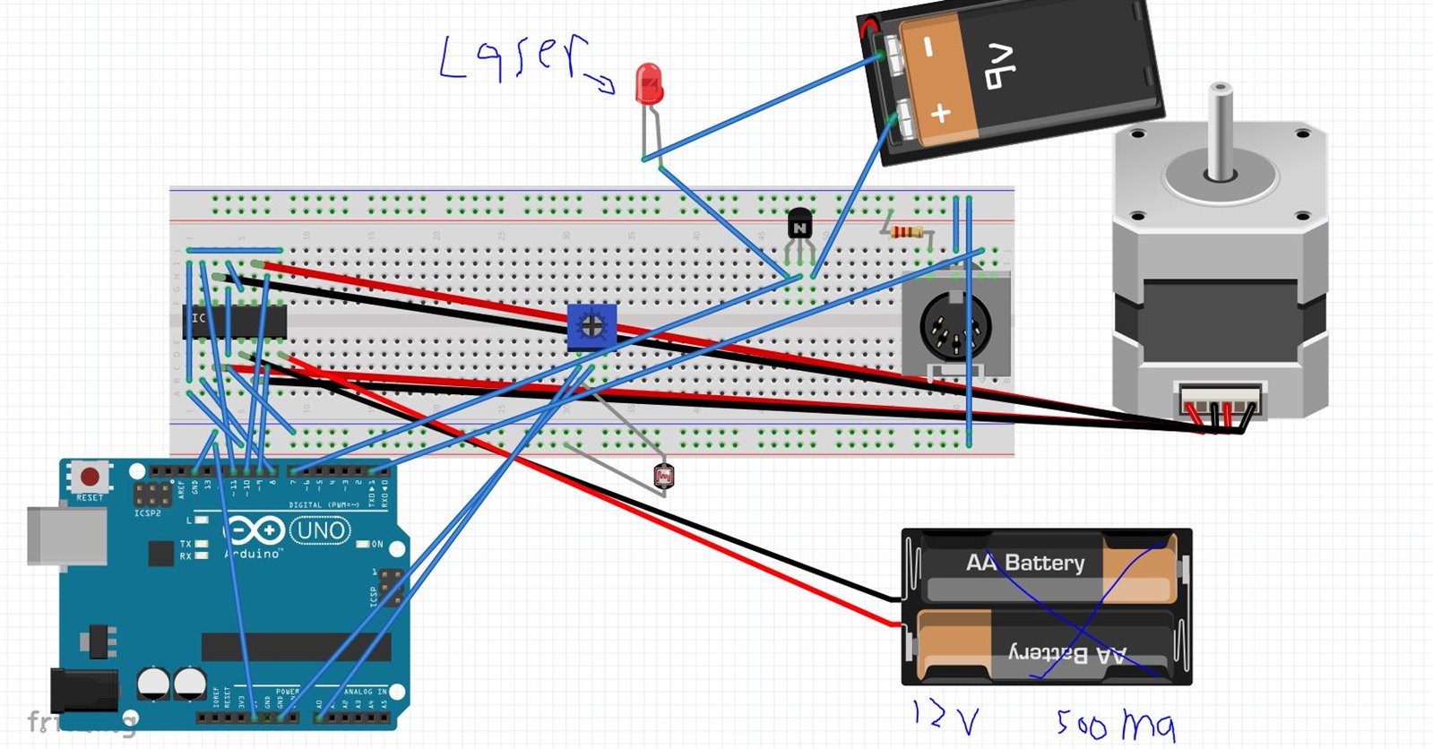
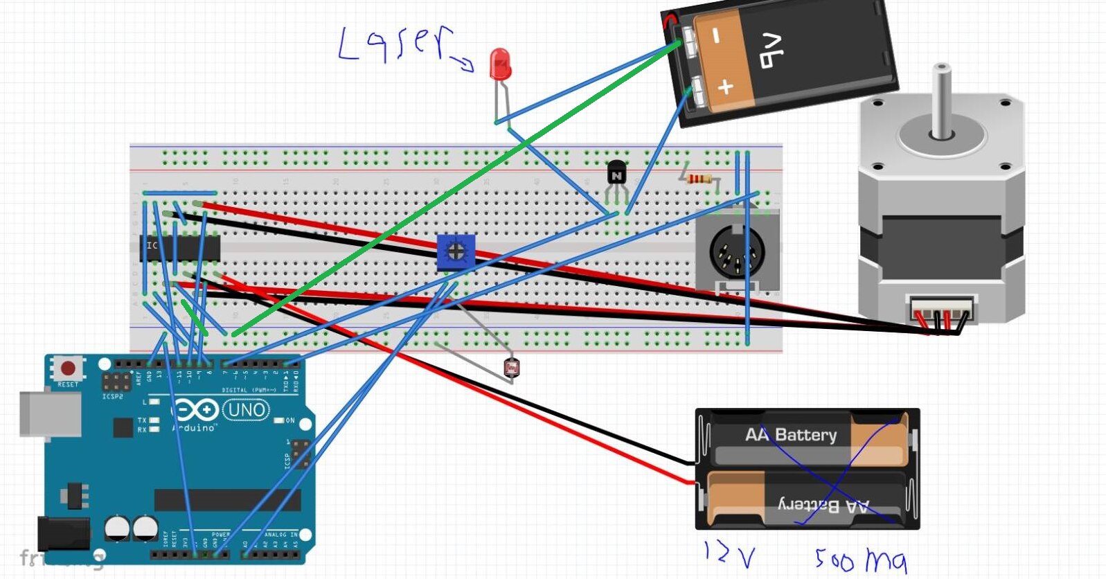
This instructable really interested me, Frameless Laser Harp - 4 , but i've never worked with steppers before.  the stepper i got has 4 wires, but the stepper in the instructable has 6.  on page 2 there is a wiring guide, but that wasn't very helpful to me, i didn't really understand what i'm supposed to do with the wires.  This is the stepper i have, https://www.sparkfun.com/products/10551?gclid=Cj0KEQiApruyBRCFqoDu1pbk9rkBEiQAF8EFdVmEBorGt6koPmFkaibEpRmZ94Z6r8BWhmTqAL… .  Any ideas?

  • Sign in to reply
  • Cancel

Top Replies

  • Robert Peter Oakes
    Robert Peter Oakes over 9 years ago in reply to gub11 +2 suggested
    reverse... to change direction lol now more seriously... then you wire up the stepper motor, if it is not going in the direction you expect for the command your giving then you can change the code or simply…
  • Robert Peter Oakes
    Robert Peter Oakes over 9 years ago +1
    Here is an excelent resource regarding steppers and how they work http://www.geckodrive.com/support.html I found this to be very helpfull in setting up my CNC project your stepper is a classic 4 wire …
  • Robert Peter Oakes
    Robert Peter Oakes over 9 years ago in reply to gub11 +1
    All Grounds (0V) should go together, the ground of the 12V, the 5V etc all are connected together at a common point the 5V goes to all those pins because it is 5V logic input to the chip and those pins…
Parents
  • Robert Peter Oakes
    0 Robert Peter Oakes over 9 years ago

    Here is an excelent resource regarding steppers and how they work

    http://www.geckodrive.com/support.html


    I found this to be very helpfull in setting up my CNC project


    your stepper is a classic 4 wire / 2 coil 7.5deg per step so 360/7.5 = 48 full steps per revolution


    also it looks like the black and orange are one coil and the brown/yellow the other


    if you want to reverse the direction in hardware then simply swap the connection of black and orange (Put the black where the orange was and the orange where the black was) or do the similar thing with the other coil wires


    Hope this helps, if you need more info then just ask

    • Cancel
    • Vote Up +1 Vote Down
    • Sign in to reply
    • Verify Answer
    • Cancel
  • gub11
    0 gub11 over 9 years ago in reply to Robert Peter Oakes

    What do you mean reverse? ND when u day put the orange where the black is, do u mean up the orange wire into where the black wire is supposed to go on the Ic? Also, I still don't know how to wire the two common wires, 1 per coil.

    • Cancel
    • Vote Up 0 Vote Down
    • Sign in to reply
    • Verify Answer
    • Cancel
  • gub11
    0 gub11 over 9 years ago in reply to jc2048

    jc2048 where do I get heatsinking?

    • Cancel
    • Vote Up 0 Vote Down
    • Sign in to reply
    • Verify Answer
    • Cancel
  • Robert Peter Oakes
    0 Robert Peter Oakes over 9 years ago in reply to gub11

    an old motherboard and pull one from the small chips on the board is one possibility if you have access, if not there are plenty available from element14 (Newark / Farnell) or even ebay, search for stepper controller heatsinks and it should bring something up but as Gabriel stated, for the low current your switching, you probably wont need one, when you are running it, feel the top of the chip with the back of your hand or carefully with a finger, if you cant keep you skin in contact for more than  a few seconds then you need a heatsink, otherwise your probably good to go


    Peter

    • Cancel
    • Vote Up 0 Vote Down
    • Sign in to reply
    • Verify Answer
    • Cancel
  • mcb1
    0 mcb1 over 9 years ago in reply to Robert Peter Oakes

    I always like the wet finger.

    It gives extra time for the slow brain to register the finger is saying "S..T THIS IS HOT" ...image

    • Cancel
    • Vote Up +1 Vote Down
    • Sign in to reply
    • Verify Answer
    • Cancel
  • Robert Peter Oakes
    0 Robert Peter Oakes over 9 years ago in reply to mcb1

    and the sound of sizzling probably will reach the brain faster too image

    • Cancel
    • Vote Up +1 Vote Down
    • Sign in to reply
    • Verify Answer
    • Cancel
  • mcb1
    0 mcb1 over 9 years ago in reply to Robert Peter Oakes

    Funny you should say that because I have witnessed that. image


    A funnier thing was a guy at work who was so used to working with transistors and fingering them, that the first valve receiver he worked on, he got a belt of the grid cap ...image

    • Cancel
    • Vote Up +1 Vote Down
    • Sign in to reply
    • Verify Answer
    • Cancel
  • jc2048
    0 jc2048 over 9 years ago in reply to jc2048

    In case it helps, this is how the temperature calculation works for the chip. If you are working with different currents to what I've assumed here (400mA in each coil) you can rework it accordingly.


    The bridge has an upper transistor and a lower transistor on each end of the coil. For this application, if an upper transistor is on you also have the opposite lower transistor on. If the lower transistor is on, the opposite upper is on. That's how you get the current to flow in one direction or the other through the coil.


    Note from that there is always one upper and one lower on at any time.


    Looking at page 6 of the datasheet [section 7.6 Typical Characteristics] you can see that for 400mA the upper transistor drops about 1.1V.


    So that's a dissipation of 1.1V x 0.4A = 0.44W. That ends up as heat in the chip.


    The bottom transistor drops about 0.9V, so that one is a dissipation of 0.9V x 0.4A = 0.36W


    Total for the two is 0.8W. Since there are two coils that gives a grand total of 1.6W.


    Although the output transistors are most of the dissipation, the rest of the circuitry does take some current too. The datasheet gives a max of 70mA on the +5V supply, but that's for all outputs low; let's average the figures for all low and all high and go for 50mA which adds 5V x 0.05A = .25W to our dissipation.


    So the total for the chip is 1.85W.


    That's a lot for a DIL package. You wouldn't expect an IC to disspate more than 0.5-1W without extra help (very variable, depending on how the chip is mounted inside, so always refer to the datasheet and don't guess).


    The datasheet says the thermal resistance of the part is 60C/W. So, if we have 1.85W of heat flowing from the chip to the outside, we'll have a temperature rise of 111C. That's a temperature rise above whatever the ambient temperature around the package is. For an ambient of 25C, that means the chip inside will reach a temperature of 136C. The datasheet recommends a junction temperature of no more than 125C, so it looks like you should use some heatsinking.


    The problem for you, even if you're happy to run it above the recommended figure, is that if you have it in a confined space (without forced cooling) the ambient temperature will rise and may take you to the point where it shuts down. (You won't damage the part because it has a temperature sensor and shuts itself down when the chip gets to 150C or so, but it's always a bit mysterious when you have a chip that doesn't work for a while and then suddenly springs into life again when it's cooled down a bit.)

    • Cancel
    • Vote Up 0 Vote Down
    • Sign in to reply
    • Verify Answer
    • Cancel
  • gub11
    0 gub11 over 9 years ago in reply to jc2048

    jc2048

    That's really helpful, I looked for heatsinking on ebay and element14's store, but couldn't find anything, coudl you link me some cheap heatsinking (i live in the US). 

    Robert Peter Oakes

    I finally got the stepper driver and I put it all together, but I am having a few issues that I don't really know how to diagnose.  I did some trial and error, but that could only help so much.  First of all, the laser doesn't turn on, second the stepper has an odd pattern of off and on, when i think it's supposed to stay on at a constant speed.  I'll take a video of that and show a diagram of how I have it wired up when I get home.

    Thanks,
    Gabe

    • Cancel
    • Vote Up 0 Vote Down
    • Sign in to reply
    • Verify Answer
    • Cancel
  • Robert Peter Oakes
    0 Robert Peter Oakes over 9 years ago in reply to gub11

    looking forward to the video so I can help diagnose the issue


    Can you also post the code you are using and the wiring sketch you ended up with when you post the video


    Thanks


    Peter

    • Cancel
    • Vote Up 0 Vote Down
    • Sign in to reply
    • Verify Answer
    • Cancel
  • jc2048
    0 jc2048 over 9 years ago in reply to gub11

    Sorry, I'm not in the US.


    This is a glue-on type:

    http://www.newark.com/fischer-elektronik/ick-14-16-l/heat-sink/dp/35M3896


    This is a clip-on type:

    http://www.newark.com/aavid-thermalloy/580200b00000g/heat-sink/dp/18M8201


    The clip-on type is more expensive, but you can reuse it.


    Whether it makes sense for you to buy from Newark I don't know.


    TI really intended you to use the pcb, either by passing the heat down to a ground plane on a multi-layer board, or by having an area of copper next to the chip on either side on a two-layer board. The package resin doesn't conduct heat very well and they've engineered the chip to get as much of the heat down the ground pins as possible so although you'd certainly be helping with a heatsink on the top it's not as good value as taking the heat from those pins if you can.

    • Cancel
    • Vote Up 0 Vote Down
    • Sign in to reply
    • Verify Answer
    • Cancel
  • gub11
    0 gub11 over 9 years ago in reply to Robert Peter Oakes

    Robert Peter Oakes

    Diagram is below and here is the link to the youtube video.  https://youtu.be/T0Lmc4enkbg

    diagram:  Imgur: The most awesome images on the Internet

    Code:

    int LaserState = LOW;                    // The variable that stores the state of the laser beam.
    int sensor = 8 ;                         // Change this value to calibrate your harp's sensor
    int delaylaser = 5;                     // If you increase this, the laser will be brighter, but the harp will be less fluid
    int delaymotor = 3;                     // This variable affects the speed, and fluidity of the harp.
    
    
    int LaserPin =  7;                       // Tell the arduino that the laser is on pin 7
    
    
    int motorPin1 = 8;                      //Use these names for the pin numbers.
    int motorPin2 = 9;
    int motorPin3 = 10;
    int motorPin4 = 11;
    
    
    int note9 = 0x61;
    int note8 = 0x63;
    int note7 = 0x64;
    int note6 = 0x66;
    int note5 = 0x68;
    int note4 = 0x70;
    int note3 = 0x71;
    int note2 = 0x40;
    int note1 = 0x47;
    
    
    int a, b, c, d, e, f, g, h, i = 0;       // Iniating the note status markers.
    
    
    void setup()
    {


      pinMode(8, OUTPUT);                    // Setup for the motor.
      pinMode(9, OUTPUT);
      pinMode(10, OUTPUT);
      pinMode(11, OUTPUT);


      pinMode(LaserPin, OUTPUT);            // Setup for laser.


      pinMode(13, OUTPUT);                 // Setup for status led.


      Serial.begin(31250);                 //  Start a serial communication channel for MIDI
    }
    
    
    void noteOn(int cmd, int pitch, int velocity)     // Function to play the notes
    {
      Serial.write(cmd);
      Serial.write(pitch);
      Serial.write(velocity);
    }
    
    
    void loop()
    {
    
    
      digitalWrite(LaserPin, HIGH);               // Turn on the laser for the 1st beam.
      delay(delaylaser);
    
    
      if ( (analogRead(0) > sensor ) && (a == 0) ) // If the sensor gets a signal, and the not is not playing:
    
    
      {
      digitalWrite(13, HIGH);       // Switch on status led.
      noteOn(0x90, note1, 0x7F);    // Play note 1
      a++;                          // Change the status variable to one.
      }


      else if(analogRead(0) < sensor )             // If the sensor does not get a signal:
    
    
      {
      digitalWrite(13, LOW);         // Switch off the status led.
      noteOn(0x90, note1, 0x00);     // Stop playing note 1.
      a = 0;                         // Change the status variable to zero.
      }


      digitalWrite(LaserPin, LOW);                // Turn off the Laser.


      digitalWrite(motorPin1, HIGH);             // Move the motor to create the second beam.( One step forward)
      digitalWrite(motorPin2, LOW);
      digitalWrite(motorPin3, LOW);
      digitalWrite(motorPin4, LOW);
      delay(delaymotor);                          // Small pause


      digitalWrite(LaserPin, HIGH);              // Turn on the laser for the 2nd beam.
      delay(delaylaser);
    
    
      if( (analogRead(0) > sensor ) && (b == 0) ) // If the sensor gets a signal, and the not is not playing:
    
    
      {
      digitalWrite(13, HIGH);              // Switch on status led.
      noteOn(0x90, note2, 0x7F);           // Play note 2
      b++;                                 // Change the status variable to one.
      }


      else if(analogRead(0) < sensor )           // If the sensor does not get a signal:
    
    
      {
      digitalWrite(13, LOW);          // Switch off the status led.
      noteOn(0x90, note2, 0x00);      // Stop playing note 2.
      b = 0;                          // Change the status variable to zero.
      }
    
    
      digitalWrite(LaserPin, LOW);                    // Turn off the Laser.


      digitalWrite(motorPin1, LOW);              // Move the motor to create the second beam.( One step forward)
      digitalWrite(motorPin2, HIGH);
      digitalWrite(motorPin3, LOW);
      digitalWrite(motorPin4, LOW);
      delay(delaymotor);                          // Small pause


      digitalWrite(LaserPin, HIGH);             // Turn on the laser for the 3rd beam.
      delay(delaylaser);
    
    
      if( (analogRead(0) > sensor ) && (c == 0) ) // If the sensor gets a signal, and the not is not playing:
    
    
      {
      digitalWrite(13, HIGH);       // Switch on status led.
      noteOn(0x90, note3, 0x7F);    // Play note 3
      c++;                          // Change the status variable to one.
      }


      else if(analogRead(0) < sensor )           // If the sensor does not get a signal:
      {
      digitalWrite(13, LOW);        // Switch off the status led.
      noteOn(0x90, note3, 0x00);    // Stop playing note 2.
      c = 0;                        // Change the status variable to zero.
      }
    
    
      digitalWrite(LaserPin, LOW);                 // Turn off the Laser.
    
    
      digitalWrite(motorPin1, LOW);               // Move the motor to create the third beam.( One step forward)
      digitalWrite(motorPin2, LOW);
      digitalWrite(motorPin3, HIGH);
      digitalWrite(motorPin4, LOW);
      delay(delaymotor);                            // Small pause
    
    
      // Contiue in the same way for the rest of the code.
    
    
      digitalWrite(LaserPin, HIGH);               //This is beam 4
      delay(delaylaser);
    
    
      if( (analogRead(0) > sensor ) && (d == 0) )
      {
      digitalWrite(13, HIGH);
      noteOn(0x90, note4, 0x7F);
      d++;
      }


      else if(analogRead(0) < sensor )
      {
      digitalWrite(13, LOW);
      noteOn(0x90, note4, 0x00);
      d = 0;
      }
    
    
      digitalWrite(LaserPin, LOW);


      digitalWrite(motorPin1, LOW);
      digitalWrite(motorPin2, LOW);
      digitalWrite(motorPin3, LOW);
      digitalWrite(motorPin4, HIGH);
      delay(delaymotor);


      digitalWrite(LaserPin, HIGH);                  //This is beam 5
      delay(delaylaser);
    
    
      if( (analogRead(0) > sensor ) && (e == 0) )
    
    
      {
      digitalWrite(13, HIGH);
      noteOn(0x90, note5, 0x7F);
      e++;
      }


      else if(analogRead(0) < sensor )
    
    
      {
      digitalWrite(13, LOW);
      noteOn(0x90, note5, 0x00);
      e = 0;
      }
    
    
      digitalWrite(LaserPin, LOW);


      digitalWrite(motorPin1, HIGH);
      digitalWrite(motorPin2, LOW);
      digitalWrite(motorPin3, LOW);
      digitalWrite(motorPin4, LOW);
      delay(delaymotor);


      digitalWrite(LaserPin, HIGH);                  //This is beam 6
      delay(delaylaser);
    
    
      if( (analogRead(0) > sensor ) && (f == 0) )
    
    
      {
      digitalWrite(13, HIGH);
      noteOn(0x90, note6, 0x7F);
      f++;
      }


      else if(analogRead(0) < sensor )
    
    
      {
      digitalWrite(13, LOW);
      noteOn(0x90, note6, 0x00);
      f = 0;
      }
    
    
      digitalWrite(LaserPin, LOW);
    
    
      digitalWrite(motorPin1, LOW);
      digitalWrite(motorPin2, HIGH);
      digitalWrite(motorPin3, LOW);
      digitalWrite(motorPin4, LOW);
      delay(delaymotor);


      digitalWrite(LaserPin, HIGH);                  //This is beam 7
      delay(delaylaser);
    
    
      if( (analogRead(0) > sensor ) && (g == 0) )
    
    
      {
      digitalWrite(13, HIGH);
      noteOn(0x90, note7, 0x7F);
      g++;
      }


      else if(analogRead(0) < sensor )
    
    
      {
      digitalWrite(13, LOW);
      noteOn(0x90, note7, 0x00);
      g = 0;
      }
    
    
      digitalWrite(LaserPin, LOW);


      digitalWrite(motorPin1, LOW);
      digitalWrite(motorPin2, LOW);
      digitalWrite(motorPin3, HIGH);
      digitalWrite(motorPin4, LOW);
      delay(delaymotor);


      digitalWrite(LaserPin, HIGH);                   //This is beam 8
      delay(delaylaser);
    
    
      if( (analogRead(0) > sensor ) && (h == 0) )
    
    
      {
      digitalWrite(13, HIGH);
      noteOn(0x90, note8, 0x7F);
      h++;
      }


      else if(analogRead(0) < sensor )
    
    
      {
      digitalWrite(13, LOW);
      noteOn(0x90, note8, 0x00);
      h = 0;
      }
    
    
      digitalWrite(LaserPin, LOW);


      digitalWrite(motorPin1, LOW);
      digitalWrite(motorPin2, LOW);
      digitalWrite(motorPin3, LOW);
      digitalWrite(motorPin4, HIGH);
      delay(delaymotor);


      digitalWrite(LaserPin, HIGH);    //This is beam 9
      delay(delaylaser);
    
    
      if( (analogRead(0) > sensor ) && (i == 0) )
      {
      digitalWrite(13, HIGH);
      noteOn(0x90, note9, 0x7F);
      i++;
      }
    
    
      else if(analogRead(0) < sensor )
    
    
      {
      digitalWrite(13, LOW);
      noteOn(0x90, note9, 0x00);
      i = 0;
      }


      digitalWrite(LaserPin, LOW);


      digitalWrite(motorPin1, LOW);
      digitalWrite(motorPin2, LOW);
      digitalWrite(motorPin3, HIGH);
      digitalWrite(motorPin4, LOW);
      delay(delaymotor);
    
    
      digitalWrite(LaserPin, HIGH);       //This is beam 8
      delay(delaylaser);
    
    
      if( (analogRead(0) > sensor ) && (h == 0) )
    
    
      {
      digitalWrite(13, HIGH);
      noteOn(0x90, note8, 0x7F);
      h++;
      }


      else if(analogRead(0) < sensor )
    
    
      {
      digitalWrite(13, LOW);
      noteOn(0x90, note8, 0x00);
      h = 0;
      }
    
    
      digitalWrite(LaserPin, LOW);


      digitalWrite(motorPin1, LOW);
      digitalWrite(motorPin2, HIGH);
      digitalWrite(motorPin3, LOW);
      digitalWrite(motorPin4, LOW);
      delay(delaymotor);


      digitalWrite(LaserPin, HIGH);    //This is beam 7
      delay(delaylaser);
    
    
      if( (analogRead(0) > sensor ) && (g == 0) )
    
    
      {
      digitalWrite(13, HIGH);
      noteOn(0x90, note7, 0x7F);
      g++;
      }


      else if(analogRead(0) < sensor )
      {
      digitalWrite(13, LOW);
      noteOn(0x90, note7, 0x00);
      g = 0;
      }
    
    
      digitalWrite(LaserPin, LOW);


      digitalWrite(motorPin1, HIGH);
      digitalWrite(motorPin2, LOW);
      digitalWrite(motorPin3, LOW);
      digitalWrite(motorPin4, LOW);
      delay(delaymotor);


      digitalWrite(LaserPin, HIGH);    //This is beam 6
      delay(delaylaser);
    
    
      if( (analogRead(0) > sensor ) && (f == 0) )
    
    
      {
    
    
      digitalWrite(13, HIGH);
      noteOn(0x90, note6, 0x7F);
      f++;
      }


      else if(analogRead(0) < sensor )
    
    
      {
      digitalWrite(13, LOW);
      noteOn(0x90, note6, 0x00);
      f = 0;
      }
    
    
      digitalWrite(LaserPin, LOW);


      digitalWrite(motorPin1, LOW);
      digitalWrite(motorPin2, LOW);
      digitalWrite(motorPin3, LOW);
      digitalWrite(motorPin4, HIGH);
      delay(delaymotor);


      digitalWrite(LaserPin, HIGH);    //This is beam 5
      delay(delaylaser);
    
    
      if( (analogRead(0) > sensor ) && (e == 0) )
    
    
      {
      digitalWrite(13, HIGH);
      noteOn(0x90, note5, 0x7F);
      e++;
      }


      else if(analogRead(0) < sensor )
    
    
      {
      digitalWrite(13, LOW);
      noteOn(0x90, note5, 0x00);
      e = 0;
      }
    
    
      digitalWrite(LaserPin, LOW);
    
    
      digitalWrite(motorPin1, LOW);
      digitalWrite(motorPin2, LOW);
      digitalWrite(motorPin3, HIGH);
      digitalWrite(motorPin4, LOW);
      delay(delaymotor);


      digitalWrite(LaserPin, HIGH);      //This is beam 4
      delay(delaylaser);
    
    
      if( (analogRead(0) > sensor ) && (d == 0) )
    
    
      {
      digitalWrite(13, HIGH);
      noteOn(0x90, note4, 0x7F);
      d++;
      }
    
    
      else if(analogRead(0) < sensor )
    
    
      {
      digitalWrite(13, LOW);
      noteOn(0x90, note4, 0x00);
      d = 0;
      }
    
    
      digitalWrite(LaserPin, LOW);
    
    
      digitalWrite(motorPin1, LOW);
      digitalWrite(motorPin2, HIGH);
      digitalWrite(motorPin3, LOW);
      digitalWrite(motorPin4, LOW);
      delay(delaymotor);


      digitalWrite(LaserPin, HIGH);    //This is beam 3
      delay(delaylaser);
    
    
      if( (analogRead(0) > sensor ) && (c == 0) )
      {
      digitalWrite(13, HIGH);
      noteOn(0x90, note3, 0x7F);
      c++;
      }


      else if(analogRead(0) < sensor )
    
    
      {
      digitalWrite(13, LOW);
      noteOn(0x90, note3, 0x00);
      c = 0;
      }
    
    
      digitalWrite(LaserPin, LOW);
    
    
      digitalWrite(motorPin1, HIGH);
      digitalWrite(motorPin2, LOW);
      digitalWrite(motorPin3, LOW);
      digitalWrite(motorPin4, LOW);
      delay(delaymotor);
    
    
      digitalWrite(LaserPin, HIGH);    //This is beam 2
      delay(delaylaser);
    
    
      if( (analogRead(0) > sensor ) && (b == 0) )
    
    
      {
      digitalWrite(13, HIGH);
      noteOn(0x90, note2, 0x7F);
      b++;
      }


      else if(analogRead(0) < sensor )
    
    
      {
      digitalWrite(13, LOW);
      noteOn(0x90, note2, 0x00);
      b = 0;
      }
    
    
      digitalWrite(LaserPin, LOW);


      digitalWrite(motorPin1, LOW);
      digitalWrite(motorPin2, LOW);
      digitalWrite(motorPin3, LOW);
      digitalWrite(motorPin4, HIGH);
      delay(delaymotor);


    // Back to top.
    
    
    }

    image

    • Cancel
    • Vote Up 0 Vote Down
    • Sign in to reply
    • Verify Answer
    • Cancel
Reply
  • gub11
    0 gub11 over 9 years ago in reply to Robert Peter Oakes

    Robert Peter Oakes

    Diagram is below and here is the link to the youtube video.  https://youtu.be/T0Lmc4enkbg

    diagram:  Imgur: The most awesome images on the Internet

    Code:

    int LaserState = LOW;                    // The variable that stores the state of the laser beam.
    int sensor = 8 ;                         // Change this value to calibrate your harp's sensor
    int delaylaser = 5;                     // If you increase this, the laser will be brighter, but the harp will be less fluid
    int delaymotor = 3;                     // This variable affects the speed, and fluidity of the harp.
    
    
    int LaserPin =  7;                       // Tell the arduino that the laser is on pin 7
    
    
    int motorPin1 = 8;                      //Use these names for the pin numbers.
    int motorPin2 = 9;
    int motorPin3 = 10;
    int motorPin4 = 11;
    
    
    int note9 = 0x61;
    int note8 = 0x63;
    int note7 = 0x64;
    int note6 = 0x66;
    int note5 = 0x68;
    int note4 = 0x70;
    int note3 = 0x71;
    int note2 = 0x40;
    int note1 = 0x47;
    
    
    int a, b, c, d, e, f, g, h, i = 0;       // Iniating the note status markers.
    
    
    void setup()
    {


      pinMode(8, OUTPUT);                    // Setup for the motor.
      pinMode(9, OUTPUT);
      pinMode(10, OUTPUT);
      pinMode(11, OUTPUT);


      pinMode(LaserPin, OUTPUT);            // Setup for laser.


      pinMode(13, OUTPUT);                 // Setup for status led.


      Serial.begin(31250);                 //  Start a serial communication channel for MIDI
    }
    
    
    void noteOn(int cmd, int pitch, int velocity)     // Function to play the notes
    {
      Serial.write(cmd);
      Serial.write(pitch);
      Serial.write(velocity);
    }
    
    
    void loop()
    {
    
    
      digitalWrite(LaserPin, HIGH);               // Turn on the laser for the 1st beam.
      delay(delaylaser);
    
    
      if ( (analogRead(0) > sensor ) && (a == 0) ) // If the sensor gets a signal, and the not is not playing:
    
    
      {
      digitalWrite(13, HIGH);       // Switch on status led.
      noteOn(0x90, note1, 0x7F);    // Play note 1
      a++;                          // Change the status variable to one.
      }


      else if(analogRead(0) < sensor )             // If the sensor does not get a signal:
    
    
      {
      digitalWrite(13, LOW);         // Switch off the status led.
      noteOn(0x90, note1, 0x00);     // Stop playing note 1.
      a = 0;                         // Change the status variable to zero.
      }


      digitalWrite(LaserPin, LOW);                // Turn off the Laser.


      digitalWrite(motorPin1, HIGH);             // Move the motor to create the second beam.( One step forward)
      digitalWrite(motorPin2, LOW);
      digitalWrite(motorPin3, LOW);
      digitalWrite(motorPin4, LOW);
      delay(delaymotor);                          // Small pause


      digitalWrite(LaserPin, HIGH);              // Turn on the laser for the 2nd beam.
      delay(delaylaser);
    
    
      if( (analogRead(0) > sensor ) && (b == 0) ) // If the sensor gets a signal, and the not is not playing:
    
    
      {
      digitalWrite(13, HIGH);              // Switch on status led.
      noteOn(0x90, note2, 0x7F);           // Play note 2
      b++;                                 // Change the status variable to one.
      }


      else if(analogRead(0) < sensor )           // If the sensor does not get a signal:
    
    
      {
      digitalWrite(13, LOW);          // Switch off the status led.
      noteOn(0x90, note2, 0x00);      // Stop playing note 2.
      b = 0;                          // Change the status variable to zero.
      }
    
    
      digitalWrite(LaserPin, LOW);                    // Turn off the Laser.


      digitalWrite(motorPin1, LOW);              // Move the motor to create the second beam.( One step forward)
      digitalWrite(motorPin2, HIGH);
      digitalWrite(motorPin3, LOW);
      digitalWrite(motorPin4, LOW);
      delay(delaymotor);                          // Small pause


      digitalWrite(LaserPin, HIGH);             // Turn on the laser for the 3rd beam.
      delay(delaylaser);
    
    
      if( (analogRead(0) > sensor ) && (c == 0) ) // If the sensor gets a signal, and the not is not playing:
    
    
      {
      digitalWrite(13, HIGH);       // Switch on status led.
      noteOn(0x90, note3, 0x7F);    // Play note 3
      c++;                          // Change the status variable to one.
      }


      else if(analogRead(0) < sensor )           // If the sensor does not get a signal:
      {
      digitalWrite(13, LOW);        // Switch off the status led.
      noteOn(0x90, note3, 0x00);    // Stop playing note 2.
      c = 0;                        // Change the status variable to zero.
      }
    
    
      digitalWrite(LaserPin, LOW);                 // Turn off the Laser.
    
    
      digitalWrite(motorPin1, LOW);               // Move the motor to create the third beam.( One step forward)
      digitalWrite(motorPin2, LOW);
      digitalWrite(motorPin3, HIGH);
      digitalWrite(motorPin4, LOW);
      delay(delaymotor);                            // Small pause
    
    
      // Contiue in the same way for the rest of the code.
    
    
      digitalWrite(LaserPin, HIGH);               //This is beam 4
      delay(delaylaser);
    
    
      if( (analogRead(0) > sensor ) && (d == 0) )
      {
      digitalWrite(13, HIGH);
      noteOn(0x90, note4, 0x7F);
      d++;
      }


      else if(analogRead(0) < sensor )
      {
      digitalWrite(13, LOW);
      noteOn(0x90, note4, 0x00);
      d = 0;
      }
    
    
      digitalWrite(LaserPin, LOW);


      digitalWrite(motorPin1, LOW);
      digitalWrite(motorPin2, LOW);
      digitalWrite(motorPin3, LOW);
      digitalWrite(motorPin4, HIGH);
      delay(delaymotor);


      digitalWrite(LaserPin, HIGH);                  //This is beam 5
      delay(delaylaser);
    
    
      if( (analogRead(0) > sensor ) && (e == 0) )
    
    
      {
      digitalWrite(13, HIGH);
      noteOn(0x90, note5, 0x7F);
      e++;
      }


      else if(analogRead(0) < sensor )
    
    
      {
      digitalWrite(13, LOW);
      noteOn(0x90, note5, 0x00);
      e = 0;
      }
    
    
      digitalWrite(LaserPin, LOW);


      digitalWrite(motorPin1, HIGH);
      digitalWrite(motorPin2, LOW);
      digitalWrite(motorPin3, LOW);
      digitalWrite(motorPin4, LOW);
      delay(delaymotor);


      digitalWrite(LaserPin, HIGH);                  //This is beam 6
      delay(delaylaser);
    
    
      if( (analogRead(0) > sensor ) && (f == 0) )
    
    
      {
      digitalWrite(13, HIGH);
      noteOn(0x90, note6, 0x7F);
      f++;
      }


      else if(analogRead(0) < sensor )
    
    
      {
      digitalWrite(13, LOW);
      noteOn(0x90, note6, 0x00);
      f = 0;
      }
    
    
      digitalWrite(LaserPin, LOW);
    
    
      digitalWrite(motorPin1, LOW);
      digitalWrite(motorPin2, HIGH);
      digitalWrite(motorPin3, LOW);
      digitalWrite(motorPin4, LOW);
      delay(delaymotor);


      digitalWrite(LaserPin, HIGH);                  //This is beam 7
      delay(delaylaser);
    
    
      if( (analogRead(0) > sensor ) && (g == 0) )
    
    
      {
      digitalWrite(13, HIGH);
      noteOn(0x90, note7, 0x7F);
      g++;
      }


      else if(analogRead(0) < sensor )
    
    
      {
      digitalWrite(13, LOW);
      noteOn(0x90, note7, 0x00);
      g = 0;
      }
    
    
      digitalWrite(LaserPin, LOW);


      digitalWrite(motorPin1, LOW);
      digitalWrite(motorPin2, LOW);
      digitalWrite(motorPin3, HIGH);
      digitalWrite(motorPin4, LOW);
      delay(delaymotor);


      digitalWrite(LaserPin, HIGH);                   //This is beam 8
      delay(delaylaser);
    
    
      if( (analogRead(0) > sensor ) && (h == 0) )
    
    
      {
      digitalWrite(13, HIGH);
      noteOn(0x90, note8, 0x7F);
      h++;
      }


      else if(analogRead(0) < sensor )
    
    
      {
      digitalWrite(13, LOW);
      noteOn(0x90, note8, 0x00);
      h = 0;
      }
    
    
      digitalWrite(LaserPin, LOW);


      digitalWrite(motorPin1, LOW);
      digitalWrite(motorPin2, LOW);
      digitalWrite(motorPin3, LOW);
      digitalWrite(motorPin4, HIGH);
      delay(delaymotor);


      digitalWrite(LaserPin, HIGH);    //This is beam 9
      delay(delaylaser);
    
    
      if( (analogRead(0) > sensor ) && (i == 0) )
      {
      digitalWrite(13, HIGH);
      noteOn(0x90, note9, 0x7F);
      i++;
      }
    
    
      else if(analogRead(0) < sensor )
    
    
      {
      digitalWrite(13, LOW);
      noteOn(0x90, note9, 0x00);
      i = 0;
      }


      digitalWrite(LaserPin, LOW);


      digitalWrite(motorPin1, LOW);
      digitalWrite(motorPin2, LOW);
      digitalWrite(motorPin3, HIGH);
      digitalWrite(motorPin4, LOW);
      delay(delaymotor);
    
    
      digitalWrite(LaserPin, HIGH);       //This is beam 8
      delay(delaylaser);
    
    
      if( (analogRead(0) > sensor ) && (h == 0) )
    
    
      {
      digitalWrite(13, HIGH);
      noteOn(0x90, note8, 0x7F);
      h++;
      }


      else if(analogRead(0) < sensor )
    
    
      {
      digitalWrite(13, LOW);
      noteOn(0x90, note8, 0x00);
      h = 0;
      }
    
    
      digitalWrite(LaserPin, LOW);


      digitalWrite(motorPin1, LOW);
      digitalWrite(motorPin2, HIGH);
      digitalWrite(motorPin3, LOW);
      digitalWrite(motorPin4, LOW);
      delay(delaymotor);


      digitalWrite(LaserPin, HIGH);    //This is beam 7
      delay(delaylaser);
    
    
      if( (analogRead(0) > sensor ) && (g == 0) )
    
    
      {
      digitalWrite(13, HIGH);
      noteOn(0x90, note7, 0x7F);
      g++;
      }


      else if(analogRead(0) < sensor )
      {
      digitalWrite(13, LOW);
      noteOn(0x90, note7, 0x00);
      g = 0;
      }
    
    
      digitalWrite(LaserPin, LOW);


      digitalWrite(motorPin1, HIGH);
      digitalWrite(motorPin2, LOW);
      digitalWrite(motorPin3, LOW);
      digitalWrite(motorPin4, LOW);
      delay(delaymotor);


      digitalWrite(LaserPin, HIGH);    //This is beam 6
      delay(delaylaser);
    
    
      if( (analogRead(0) > sensor ) && (f == 0) )
    
    
      {
    
    
      digitalWrite(13, HIGH);
      noteOn(0x90, note6, 0x7F);
      f++;
      }


      else if(analogRead(0) < sensor )
    
    
      {
      digitalWrite(13, LOW);
      noteOn(0x90, note6, 0x00);
      f = 0;
      }
    
    
      digitalWrite(LaserPin, LOW);


      digitalWrite(motorPin1, LOW);
      digitalWrite(motorPin2, LOW);
      digitalWrite(motorPin3, LOW);
      digitalWrite(motorPin4, HIGH);
      delay(delaymotor);


      digitalWrite(LaserPin, HIGH);    //This is beam 5
      delay(delaylaser);
    
    
      if( (analogRead(0) > sensor ) && (e == 0) )
    
    
      {
      digitalWrite(13, HIGH);
      noteOn(0x90, note5, 0x7F);
      e++;
      }


      else if(analogRead(0) < sensor )
    
    
      {
      digitalWrite(13, LOW);
      noteOn(0x90, note5, 0x00);
      e = 0;
      }
    
    
      digitalWrite(LaserPin, LOW);
    
    
      digitalWrite(motorPin1, LOW);
      digitalWrite(motorPin2, LOW);
      digitalWrite(motorPin3, HIGH);
      digitalWrite(motorPin4, LOW);
      delay(delaymotor);


      digitalWrite(LaserPin, HIGH);      //This is beam 4
      delay(delaylaser);
    
    
      if( (analogRead(0) > sensor ) && (d == 0) )
    
    
      {
      digitalWrite(13, HIGH);
      noteOn(0x90, note4, 0x7F);
      d++;
      }
    
    
      else if(analogRead(0) < sensor )
    
    
      {
      digitalWrite(13, LOW);
      noteOn(0x90, note4, 0x00);
      d = 0;
      }
    
    
      digitalWrite(LaserPin, LOW);
    
    
      digitalWrite(motorPin1, LOW);
      digitalWrite(motorPin2, HIGH);
      digitalWrite(motorPin3, LOW);
      digitalWrite(motorPin4, LOW);
      delay(delaymotor);


      digitalWrite(LaserPin, HIGH);    //This is beam 3
      delay(delaylaser);
    
    
      if( (analogRead(0) > sensor ) && (c == 0) )
      {
      digitalWrite(13, HIGH);
      noteOn(0x90, note3, 0x7F);
      c++;
      }


      else if(analogRead(0) < sensor )
    
    
      {
      digitalWrite(13, LOW);
      noteOn(0x90, note3, 0x00);
      c = 0;
      }
    
    
      digitalWrite(LaserPin, LOW);
    
    
      digitalWrite(motorPin1, HIGH);
      digitalWrite(motorPin2, LOW);
      digitalWrite(motorPin3, LOW);
      digitalWrite(motorPin4, LOW);
      delay(delaymotor);
    
    
      digitalWrite(LaserPin, HIGH);    //This is beam 2
      delay(delaylaser);
    
    
      if( (analogRead(0) > sensor ) && (b == 0) )
    
    
      {
      digitalWrite(13, HIGH);
      noteOn(0x90, note2, 0x7F);
      b++;
      }


      else if(analogRead(0) < sensor )
    
    
      {
      digitalWrite(13, LOW);
      noteOn(0x90, note2, 0x00);
      b = 0;
      }
    
    
      digitalWrite(LaserPin, LOW);


      digitalWrite(motorPin1, LOW);
      digitalWrite(motorPin2, LOW);
      digitalWrite(motorPin3, LOW);
      digitalWrite(motorPin4, HIGH);
      delay(delaymotor);


    // Back to top.
    
    
    }

    image

    • Cancel
    • Vote Up 0 Vote Down
    • Sign in to reply
    • Verify Answer
    • Cancel
Children
  • Robert Peter Oakes
    0 Robert Peter Oakes over 9 years ago in reply to gub11

    Based on this diagram it looks like none of your grounds are connected together (the 0V lines of both supplies and the arduino and the chip should all be connected together, see the green lines

    image

    based on what I am seeing this should fix the electrical by having all devices and chips connected together via the ground (0V) line


    the reason the Lazer is not turning on is that there is no ground path for the transistor to return the base current to the arduino, thats why the first green line to be added from the 9V battery

    the possible reason the stepper is not working properly is that while the 12V supply has a return path to the battery, and the arduino is connected to a pin of the chip, the two grounds are not connected and therefor maybe excessive current through the chip or something similar therefor the second green added

    • Cancel
    • Vote Up 0 Vote Down
    • Sign in to reply
    • Verify Answer
    • Cancel
  • gub11
    0 gub11 over 9 years ago in reply to Robert Peter Oakes

    Robert Peter Oakes

    I am trying it right now, but I don't understand what that would change

    • Cancel
    • Vote Up 0 Vote Down
    • Sign in to reply
    • Verify Answer
    • Cancel
  • gub11
    0 gub11 over 9 years ago in reply to Robert Peter Oakes

    Robert Peter Oakes

    After doing exactley what you did in the diagram, the laser works now(YAY), but now i just need the stepper to stop being weird.  Now when i turn it on the stepper moves, stops for like half a second, then moves again

    • Cancel
    • Vote Up 0 Vote Down
    • Sign in to reply
    • Verify Answer
    • Cancel
  • Robert Peter Oakes
    0 Robert Peter Oakes over 9 years ago in reply to gub11

    Glad were getting there, I dont have the chip you have but tomorow I will look at the sketch for you, its 2:30AM here so im off to bed image


    Can you take a really good picture of your breadboard and post it, as high a resolution as you can so I can see all your connections


    I know you posted the fritzing diagram but I need to see what you did vs what you should have done image


    Thanks

    • Cancel
    • Vote Up 0 Vote Down
    • Sign in to reply
    • Verify Answer
    • Cancel
  • gub11
    0 gub11 over 9 years ago in reply to Robert Peter Oakes

    Ok, here it is, but BTW, the fritzing has all of the exact connections i have if u need more of a reference.  I took 7 pictures just in case any connections were unclear, let me know if you have any questions about them.

    Imgur: The most awesome images on the Internet

    they are 5312x2988 (that should suffice image)

    • Cancel
    • Vote Up 0 Vote Down
    • Sign in to reply
    • Verify Answer
    • Cancel
  • gub11
    0 gub11 over 9 years ago in reply to gub11

    forgot to do the Robert Peter Oakes

    • Cancel
    • Vote Up 0 Vote Down
    • Sign in to reply
    • Verify Answer
    • Cancel
  • mcb1
    0 mcb1 over 9 years ago in reply to Robert Peter Oakes

    I'm thinking there is a distinct lack of decoupling caps along with some meaty Filter caps.

    I suspect that removing the power to the common of the stepper (or adding a series resistor) stops the issues.


    Mark

    • Cancel
    • Vote Up 0 Vote Down
    • Sign in to reply
    • Verify Answer
    • Cancel
  • gub11
    0 gub11 over 9 years ago in reply to mcb1

    mcb1 could you please explain a bit more, possibly with a diagram?

    • Cancel
    • Vote Up 0 Vote Down
    • Sign in to reply
    • Verify Answer
    • Cancel
  • mcb1
    0 mcb1 over 9 years ago in reply to gub11

    Sorry I'm busy with work and no internet at home.

    You could always try this link

    https://www.google.com/#q=decoupling+caps


    Peter is handling it and the comment was made to him as a possible difference.


    Mark

    • Cancel
    • Vote Up 0 Vote Down
    • Sign in to reply
    • Verify Answer
    • Cancel
element14 Community

element14 is the first online community specifically for engineers. Connect with your peers and get expert answers to your questions.

  • Members
  • Learn
  • Technologies
  • Challenges & Projects
  • Products
  • Store
  • About Us
  • Feedback & Support
  • FAQs
  • Terms of Use
  • Privacy Policy
  • Legal and Copyright Notices
  • Sitemap
  • Cookies

An Avnet Company © 2025 Premier Farnell Limited. All Rights Reserved.

Premier Farnell Ltd, registered in England and Wales (no 00876412), registered office: Farnell House, Forge Lane, Leeds LS12 2NE.

ICP 备案号 10220084.

Follow element14

  • X
  • Facebook
  • linkedin
  • YouTube