element14 Community
element14 Community
    Register Log In
  • Site
  • Search
  • Log In Register
  • About Us
  • Community Hub
    Community Hub
    • What's New on element14
    • Feedback and Support
    • Benefits of Membership
    • Personal Blogs
    • Members Area
    • Achievement Levels
  • Learn
    Learn
    • Ask an Expert
    • eBooks
    • element14 presents
    • Learning Center
    • Tech Spotlight
    • STEM Academy
    • Webinars, Training and Events
    • Learning Groups
  • Technologies
    Technologies
    • 3D Printing
    • FPGA
    • Industrial Automation
    • Internet of Things
    • Power & Energy
    • Sensors
    • Technology Groups
  • Challenges & Projects
    Challenges & Projects
    • Design Challenges
    • element14 presents Projects
    • Project14
    • Arduino Projects
    • Raspberry Pi Projects
    • Project Groups
  • Products
    Products
    • Arduino
    • Avnet Boards Community
    • Dev Tools
    • Manufacturers
    • Multicomp Pro
    • Product Groups
    • Raspberry Pi
    • RoadTests & Reviews
  • Store
    Store
    • Visit Your Store
    • Choose another store...
      • Europe
      •  Austria (German)
      •  Belgium (Dutch, French)
      •  Bulgaria (Bulgarian)
      •  Czech Republic (Czech)
      •  Denmark (Danish)
      •  Estonia (Estonian)
      •  Finland (Finnish)
      •  France (French)
      •  Germany (German)
      •  Hungary (Hungarian)
      •  Ireland
      •  Israel
      •  Italy (Italian)
      •  Latvia (Latvian)
      •  
      •  Lithuania (Lithuanian)
      •  Netherlands (Dutch)
      •  Norway (Norwegian)
      •  Poland (Polish)
      •  Portugal (Portuguese)
      •  Romania (Romanian)
      •  Russia (Russian)
      •  Slovakia (Slovak)
      •  Slovenia (Slovenian)
      •  Spain (Spanish)
      •  Sweden (Swedish)
      •  Switzerland(German, French)
      •  Turkey (Turkish)
      •  United Kingdom
      • Asia Pacific
      •  Australia
      •  China
      •  Hong Kong
      •  India
      •  Korea (Korean)
      •  Malaysia
      •  New Zealand
      •  Philippines
      •  Singapore
      •  Taiwan
      •  Thailand (Thai)
      • Americas
      •  Brazil (Portuguese)
      •  Canada
      •  Mexico (Spanish)
      •  United States
      Can't find the country/region you're looking for? Visit our export site or find a local distributor.
  • Translate
  • Profile
  • Settings
Arduino
  • Products
  • More
Arduino
Arduino Forum PWM controlled ammeter question?
  • Blog
  • Forum
  • Documents
  • Quiz
  • Events
  • Polls
  • Files
  • Members
  • Mentions
  • Sub-Groups
  • Tags
  • More
  • Cancel
  • New
Join Arduino to participate - click to join for free!
Actions
  • Share
  • More
  • Cancel
Forum Thread Details
  • State Not Answered
  • Replies 9 replies
  • Subscribers 394 subscribers
  • Views 732 views
  • Users 0 members are here
  • pwm
  • arduino
Related

PWM controlled ammeter question?

Former Member
Former Member over 9 years ago

HI everyone,


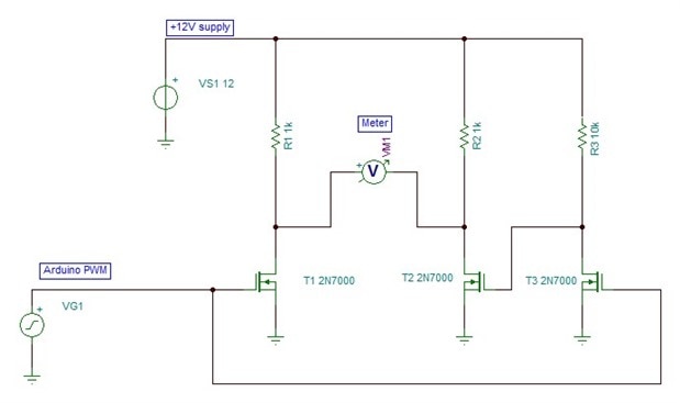
i am trying to control a zero centered ammeter with a PWM signal from an arduino.  The ammeter displays a voltage from -12v to +12v where zero volts is in the center. The needle is centered when zero.  Now the Arduino can only supply a voltage from 0 to 5 volts simulated by a PWM signal with a value from 0 to 255, where 255 is the full 5 volts.  My problem is I need to drive the ammeter from a -12v to a +12v.  I'm thinking of some kind of external circuit with a transistor to switch on and off a 12 volt source, but that will only get me half the meter to swing.  How can I get a -12v to be driven by the Arduino?  I would like to supply a PWM value of zero to the Arduino pin which would correspond to -12v, and PWM value of 128 would be 0 volts on the ammeter, and PWM value of 255 would be +12v.  Hopefully this all makes some sense.  Any help would be appreciated!


THanks Mark

  • Sign in to reply
  • Cancel

Top Replies

  • Robert Peter Oakes
    Robert Peter Oakes over 9 years ago +2
    using a simple op-amp with the + connected to the arduino output, the negative biased to 2.5V ish (You could use a pot to get it better), then supply the opamp with +- 15V (Easier than trying to use a…
  • ravi_butani
    ravi_butani over 9 years ago +2
    Here is very simple way to convert 0-5 V PWM to -2.5 to +2.5 V (avg value) converter.. the circuit below is just high pass filter which remove DC portion of PWM to make it negative and positive both..…
  • jc2048
    jc2048 over 9 years ago in reply to Robert Peter Oakes +2
    Is it easier than doing it with transistors? The above isn't a whole lot more complicated than using an op-amp (plus you don't have the problem of trying to trim the zero and getting the gain right for…
  • jc2048
    0 jc2048 over 9 years ago

    You don't really need the -12V.


    If you connect the meter to your 12V supply it reads +12V.


    If you then swap the meter terminals, it will read -12V instead of +12V.


    So, you just need a circuit that does that for you. Think about the kind of H bridge circuit that people use to drive motors in either direction, only at a much lower current.


    Further thing to think about. Your volt meter is probably an ammeter with a series resistor to get full scale with 12V. If you can get at the resistor and replace it (if you felt confident you could do that without damaging the mechanism), you could convert it to be a 5V meter and then you wouldn't need the 12V supply. [An neater alternative to taking out the existing resistor might be to solder a second resistor in parallel with it to give the overall value you want.]

    • Cancel
    • Vote Up 0 Vote Down
    • Sign in to reply
    • Verify Answer
    • Cancel
  • Robert Peter Oakes
    0 Robert Peter Oakes over 9 years ago

    using a simple op-amp with the + connected to the arduino output, the negative biased to 2.5V ish (You could use a pot to get it better), then supply the opamp with +- 15V (Easier than trying to use a rail to rail opamp or do it with transistors)


    this will provide you with the +- swing nice and easy. you could also use a simple analogue comparitor the schematic would look the same

    • Cancel
    • Vote Up +2 Vote Down
    • Sign in to reply
    • Verify Answer
    • Cancel
  • peterjcs23
    0 peterjcs23 over 9 years ago

    Use an instrumentation amplifier such as INA826, which is a rail to rail device. Power it from +/-12V. Set the gain to give +5V in +24V out but set the Vref to -12V to shift the output range down to +/-12V.

    • Cancel
    • Vote Up 0 Vote Down
    • Sign in to reply
    • Verify Answer
    • Cancel
  • ravi_butani
    0 ravi_butani over 9 years ago

    Here is very simple way to convert 0-5 V PWM to -2.5 to +2.5 V (avg value) converter..

    the circuit below is just high pass filter which remove DC portion of PWM to make it negative and positive both..


    the circuit will not work at 0% or 100% duty cycle but works just fine in range of 1% to 99% duty cycle..image

    • Cancel
    • Vote Up +2 Vote Down
    • Sign in to reply
    • Verify Answer
    • Cancel
  • Former Member
    0 Former Member over 9 years ago in reply to jc2048

    Thanks Jon for your reply.  Yes i understand that it is just an ammeter with a series resister, but i do not want to modify the meter in any way.  Your idea about an H bridge did make me think.  Thanks

    • Cancel
    • Vote Up 0 Vote Down
    • Sign in to reply
    • Verify Answer
    • Cancel
  • Former Member
    0 Former Member over 9 years ago in reply to Robert Peter Oakes

    Thanks Peter.  i do have some op amps at home i can try and use, maybe even some comparators.  i will give this a shot tonight.  ohh and by the way I really enjoy your you tube channel!


    Mark

    • Cancel
    • Vote Up 0 Vote Down
    • Sign in to reply
    • Verify Answer
    • Cancel
  • Former Member
    0 Former Member over 9 years ago in reply to peterjcs23

    That sounds like a great idea and simple, i will need to get that chip though.  At this point i am hoping to use what i have at home, several opamps, transistors.  Thanks for your input!

    • Cancel
    • Vote Up 0 Vote Down
    • Sign in to reply
    • Verify Answer
    • Cancel
  • Former Member
    0 Former Member over 9 years ago in reply to ravi_butani

    Wow, that would really make it simple.  i will give that a shot!  thanks so much!

    • Cancel
    • Vote Up 0 Vote Down
    • Sign in to reply
    • Verify Answer
    • Cancel
  • jc2048
    0 jc2048 over 9 years ago in reply to Robert Peter Oakes

    image


    Is it easier than doing it with transistors? The above isn't a whole lot more complicated than using an op-amp (plus you don't have the problem of trying to trim the zero and getting the gain right for the full-scale deflection.)

    • Cancel
    • Vote Up +2 Vote Down
    • Sign in to reply
    • Verify Answer
    • Cancel
element14 Community

element14 is the first online community specifically for engineers. Connect with your peers and get expert answers to your questions.

  • Members
  • Learn
  • Technologies
  • Challenges & Projects
  • Products
  • Store
  • About Us
  • Feedback & Support
  • FAQs
  • Terms of Use
  • Privacy Policy
  • Legal and Copyright Notices
  • Sitemap
  • Cookies

An Avnet Company © 2025 Premier Farnell Limited. All Rights Reserved.

Premier Farnell Ltd, registered in England and Wales (no 00876412), registered office: Farnell House, Forge Lane, Leeds LS12 2NE.

ICP 备案号 10220084.

Follow element14

  • X
  • Facebook
  • linkedin
  • YouTube