Hi everyone!
Recently I've started working on my own IoT project. An Airco that has no connectivity to the world (except for a remote, that I never use), to connect it to the internet.
Note: The Arduino Uno is connected with an NodeMCU ESP-12F via serial. The Arduino Uno communicates with the AC circuitry.
However, I'm facing a serious problem that stops me from continuing with the project.
The AC has got three modes, Cool, Dry and Fan. Microprocessor controls the specialised equipment inside the AC (such as the refrig., the pump etc) so there is no line going to the other control board that is high when one of the three modes is active.
The MIP (microprocessor) controls three leds to let the user know which mode is active. (here comes the, for me, very difficult part)
The GND connections of the LED's are connected to the MIP (pulls, I guess) and they are being connected to GND when a mode is active.
The challenge for me, with my Arduino Uno, is to check which GND connection of the three LED's is connected to the GND line of the external circuitry.
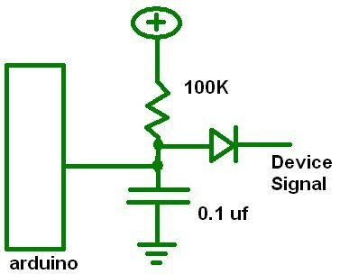
I've made a beginning, for each line I've used this setup:

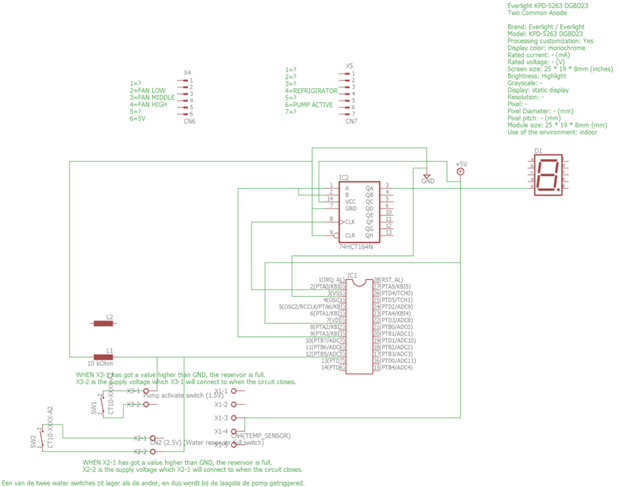
My selfmade and NOT complete schematic of the AC circuit
The values I get are usable, but they require taking loads of samples, and taking the average of all the samples, to check which line has got the lowest value (and thus is connected to GND). However, the values are fluctuating very much, and are not very accurate.
As required, the GND of the Arduino is connected to the GND of the AC circuitry.
If you want to see a few pictures of the AC circuitry, check out my Google Drive here.
The project is a hobby project, next to my school projects, so there is no deadline or something 
Thank you in advance for your help,
Tim
Message was edited by: Tim Koers Added the AC circuitry schematic