element14 Community
element14 Community
    Register Log In
  • Site
  • Search
  • Log In Register
  • About Us
  • Community Hub
    Community Hub
    • What's New on element14
    • Feedback and Support
    • Benefits of Membership
    • Personal Blogs
    • Members Area
    • Achievement Levels
  • Learn
    Learn
    • Ask an Expert
    • eBooks
    • element14 presents
    • Learning Center
    • Tech Spotlight
    • STEM Academy
    • Webinars, Training and Events
    • Learning Groups
  • Technologies
    Technologies
    • 3D Printing
    • FPGA
    • Industrial Automation
    • Internet of Things
    • Power & Energy
    • Sensors
    • Technology Groups
  • Challenges & Projects
    Challenges & Projects
    • Design Challenges
    • element14 presents Projects
    • Project14
    • Arduino Projects
    • Raspberry Pi Projects
    • Project Groups
  • Products
    Products
    • Arduino
    • Avnet Boards Community
    • Dev Tools
    • Manufacturers
    • Multicomp Pro
    • Product Groups
    • Raspberry Pi
    • RoadTests & Reviews
  • Store
    Store
    • Visit Your Store
    • Choose another store...
      • Europe
      •  Austria (German)
      •  Belgium (Dutch, French)
      •  Bulgaria (Bulgarian)
      •  Czech Republic (Czech)
      •  Denmark (Danish)
      •  Estonia (Estonian)
      •  Finland (Finnish)
      •  France (French)
      •  Germany (German)
      •  Hungary (Hungarian)
      •  Ireland
      •  Israel
      •  Italy (Italian)
      •  Latvia (Latvian)
      •  
      •  Lithuania (Lithuanian)
      •  Netherlands (Dutch)
      •  Norway (Norwegian)
      •  Poland (Polish)
      •  Portugal (Portuguese)
      •  Romania (Romanian)
      •  Russia (Russian)
      •  Slovakia (Slovak)
      •  Slovenia (Slovenian)
      •  Spain (Spanish)
      •  Sweden (Swedish)
      •  Switzerland(German, French)
      •  Turkey (Turkish)
      •  United Kingdom
      • Asia Pacific
      •  Australia
      •  China
      •  Hong Kong
      •  India
      •  Korea (Korean)
      •  Malaysia
      •  New Zealand
      •  Philippines
      •  Singapore
      •  Taiwan
      •  Thailand (Thai)
      • Americas
      •  Brazil (Portuguese)
      •  Canada
      •  Mexico (Spanish)
      •  United States
      Can't find the country/region you're looking for? Visit our export site or find a local distributor.
  • Translate
  • Profile
  • Settings
Arduino
  • Products
  • More
Arduino
Arduino Forum Power arduino using lm338k
  • Blog
  • Forum
  • Documents
  • Quiz
  • Events
  • Polls
  • Files
  • Members
  • Mentions
  • Sub-Groups
  • Tags
  • More
  • Cancel
  • New
Join Arduino to participate - click to join for free!
Actions
  • Share
  • More
  • Cancel
Forum Thread Details
  • State Verified Answer
  • Replies 16 replies
  • Answers 10 answers
  • Subscribers 394 subscribers
  • Views 2194 views
  • Users 0 members are here
  • power supply
  • lm338k
  • arduino
Related

Power arduino using lm338k

idanre1
idanre1 over 8 years ago

Hi

I have a transformer 13.8v DC.

I also have arduino nano. According to the spec, arduino can be powered from 7-12v.


I thought using http://www.ti.com/lit/ds/symlink/lm338.pdf in-order to step down the voltage to around 12v.

I have used the default scheme as mentioned in the datasheet

image


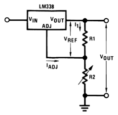
R1 is 1Kohm, R2 is 1Mohm.

image

image

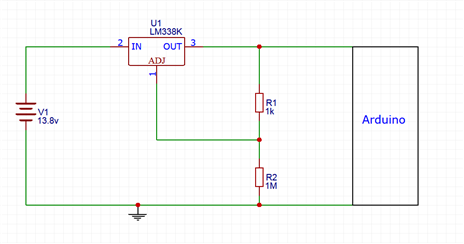
  • When Vout is un-connected to arduino - If I sample Vout using a multi-meter I get 12.19v which is great!
  • When I connect Vout to arduino's Vin port - the voltage drops down and continuously changes between 8.5v and 9.2v.
  • I want to mention the circuit is not getting hot, not the arduino and not the regulator


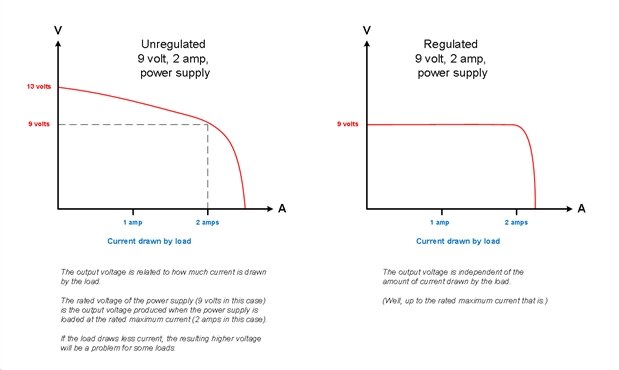
If I understand lm338k functionality, it supposed to provide a stable voltage even with load connected.


Even though ~9v is valid for powering arduino, I don't understand the phenomena.


Someone have an idea what I am doing wrong?

How can I continue the debug?


Wall-Wart photo:

I don't know why it says 7.5V, it actually outputs 13.75v when I test it with multimeter.

image


Measurement

I have just received The specified item was not found.

It has an osciliscope of up to 12v (Good enough for this task)


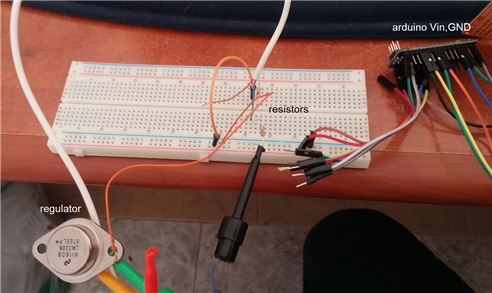
I put the measurment on Vout of the circuit above.

I have catched a trigger (8v fall edge) when I put higher load (I provde a pulse for enabling a DC motor driver) in parallel to the arduino.

image

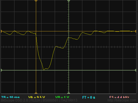
You can see the voltage it pushed from 9.5v to 6.5v during the DC activation (Higher load is attached)

When aduino is reaching towards 6.9v it then power down and the motor stops.

The signal comming back to 9.5v is because both arduino and DC motor are offline since the arduino cannot contorl over the DC anymore...


Vout on the circuit is connected to Vin of arduino.

I then put big capacitor between the 5v voltage reference of the arduino (Regulated power supply) and GND.

This keeps ardunio on 5v during this hickup.


Thanks!

Idan

  • Sign in to reply
  • Cancel

Top Replies

  • jw0752
    jw0752 over 8 years ago +4 suggested
    Hi Idan, You might consider using a regular 7809 regulator to bring the voltage down to 9 volts. You will not have to bother with resistors or adjustments. The Arduino has its own regulator to take the…
  • Robert Peter Oakes
    Robert Peter Oakes over 8 years ago in reply to gecoz +3 suggested
    While this is correct regarding the remediation of the external regulator. Thus is not the primary reason for the posters symptoms. It is bease the transformer is actually only a 7.5v one and the higher…
  • gecoz
    gecoz over 8 years ago in reply to idanre1 +2 verified
    Hi Idan, The behaviour of Vout with your original set up, I'm not sure if the choice of the values for R1 and R2 @ Vout=12V were correct. From the formula, setting R1 to 100K you get I1=12uA, as you correctly…
Parents
  • Robert Peter Oakes
    0 Robert Peter Oakes over 8 years ago

    What is the rating of the "Transformer" (Its mA or amp rating )?, can you take a picture of the label and post it here ?


    you call it a transformer but is it really a "Wall Wart". ie a power brick you plug into the wall ?


    Provide a schematic showing all the connections you making, also is anything getting warm when you are powering the arduino ?


    Peter

    • Cancel
    • Vote Up +1 Vote Down
    • Sign in to reply
    • Verify Answer
    • Cancel
  • idanre1
    0 idanre1 over 8 years ago in reply to Robert Peter Oakes

    Hi Peter

    You made some important points, I have updated the post with additional info.


    Thanks!

    Idan

    • Cancel
    • Vote Up 0 Vote Down
    • Sign in to reply
    • Verify Answer
    • Cancel
  • Robert Peter Oakes
    0 Robert Peter Oakes over 8 years ago in reply to idanre1

    A thing to mention here is that the "transformer " is 7.5v when under load. When you measure with a multimeter it only has about a 10Mohm load and so the output goes quite high fooling you into thinking it is marked wrong. What you have is an UN-REGULATED supply.


    Therefor you don't need any regulator to use it with the ardiino.  As soon as you connect it he volts will drop to the nominal 7.5 and all will be good.


    Hope this clarifies things for you

    • Cancel
    • Vote Up 0 Vote Down
    • Sign in to reply
    • Verify Answer
    • Reject Answer
    • Cancel
  • idanre1
    0 idanre1 over 8 years ago in reply to Robert Peter Oakes

    Hi Peter

    I am intrested checking your suggestion.

    What do you think is a proper load for matching 7.5v in the wall-wart? 10khom? 1kohm? Something else?


    Using Fabio's solution and assigning the right values to R1 and R2 I do get 9v when arduino+BT_module are connected as a load.


    Maybe the current consumption of the circuit is not high enough?


    Regards

    Idan

    • Cancel
    • Vote Up 0 Vote Down
    • Sign in to reply
    • Verify Answer
    • Cancel
  • gecoz
    0 gecoz over 8 years ago in reply to idanre1

    Hi Idan,


    According to your wall-wart specs, you get 7.5V @ 300mA (2.25W), therefore theoretically a load of 25ohm would do (mind, you need a 3W resistor if you want to test it without smoke!).


    Considering that the LM338 is working fine even with this unregulated supply (I never noticed you were using it before), my guess would be that the load offered by the LM338+Arduino is high, forcing the wall-wart to reduce the output current, thus increasing its output voltage to something > 12V. The only way to verify this is to actually measure the current draw from the wall-wart.


    Anyway, because of the behaviour of the unregulated power supply, I would be careful using it without any regulation circuitry: if for any reason the current draw from the wall-wart goes above the maximum 300mA, the voltage provided by the supply starts dropping below the nominal 7.5V, which could cause troubles to the Arduino Nano (Arduino needs 7V to 12V source for its internal regulator to work properly).


    Fabio.

    • Cancel
    • Vote Up 0 Vote Down
    • Sign in to reply
    • Verify Answer
    • Reject Answer
    • Cancel
  • idanre1
    0 idanre1 over 8 years ago in reply to gecoz

    Hi Fabio

    I actually don't understand your assumptions.

    You assume the wall wart output voltage is linear to the load (and current).

    I thought the 300mA is just the maximum average current that can be drawn.

    Why you assume the voltage is linear to the current?


    I accept the assumption you have min threshold for reaching7.5v as Peter mentioned, but why you say this will only happen in max current?


    Idan

    • Cancel
    • Vote Up 0 Vote Down
    • Sign in to reply
    • Verify Answer
    • Cancel
  • gecoz
    0 gecoz over 8 years ago in reply to idanre1

    Hi Idan,


    My assumption is perhaps overly simplified. Unregulated power supply typically is designed for "matching" loads, where you know what voltage and current the load will need (within known tolerance). This "matching" is needed, as unregulated power supply output voltage is affected both by the input voltage variation and varying load conditions. Therefore, to simplify, I used the nominal values for voltage and current to calculate a nominal power of the wall-wart. With unregulated supply, the current rating you find on the label is indeed the max output current (independently from the output voltage), but the nominal output voltage 7.5V does give you the voltage rating for your load, thus I wrote the nominal power is 2.25W. This does not mean that 7.5V are only guaranteed at @ 300mA, but the values written on the label do give you an indication on what to expect. What I was suggesting is that, using a purely resistive load, you can test this condition by "forcing" the wall-wart to give the load its max current, and the 25ohm resistor would make sure the voltage across the load is matching the nominal output voltage. I'm not assuming a linear dependency between output voltage and current to the load, the test I was suggesting above is only a "single point" test of the supply on the V-I curve for the power supply, and in the special case of purely resistive load. In general, the dependency V-I is non linear, but can be approximated as linear for output currents from 0 up to max output current, but becomes strongly non-linear as the current grows greater than the max output current.


    If you look at the plots below, perhaps my suggestion will become clearer (this is just an example):


    image


    I hope this explains my thinking image

    Fabio.

    • Cancel
    • Vote Up 0 Vote Down
    • Sign in to reply
    • Verify Answer
    • Reject Answer
    • Cancel
  • Robert Peter Oakes
    0 Robert Peter Oakes over 8 years ago in reply to idanre1

    The solution right now is working but the minute you increase the load further it will fail again as the transformer is nominally rated for 7.5v at upto 300mA but as it is unregulated it's voltage will vary with load, more load less volts.....


    The load needed to see if the volts is correct is simple i=v/r or r = v/I


    The arduino will never see the 13v ish you measured as it will always be placing some kind of load on the transformer. It may provide more than 7.5 but not more than 12 to 13 as this is the no load voltage

    • Cancel
    • Vote Up 0 Vote Down
    • Sign in to reply
    • Verify Answer
    • Reject Answer
    • Cancel
Reply
  • Robert Peter Oakes
    0 Robert Peter Oakes over 8 years ago in reply to idanre1

    The solution right now is working but the minute you increase the load further it will fail again as the transformer is nominally rated for 7.5v at upto 300mA but as it is unregulated it's voltage will vary with load, more load less volts.....


    The load needed to see if the volts is correct is simple i=v/r or r = v/I


    The arduino will never see the 13v ish you measured as it will always be placing some kind of load on the transformer. It may provide more than 7.5 but not more than 12 to 13 as this is the no load voltage

    • Cancel
    • Vote Up 0 Vote Down
    • Sign in to reply
    • Verify Answer
    • Reject Answer
    • Cancel
Children
No Data
element14 Community

element14 is the first online community specifically for engineers. Connect with your peers and get expert answers to your questions.

  • Members
  • Learn
  • Technologies
  • Challenges & Projects
  • Products
  • Store
  • About Us
  • Feedback & Support
  • FAQs
  • Terms of Use
  • Privacy Policy
  • Legal and Copyright Notices
  • Sitemap
  • Cookies

An Avnet Company © 2025 Premier Farnell Limited. All Rights Reserved.

Premier Farnell Ltd, registered in England and Wales (no 00876412), registered office: Farnell House, Forge Lane, Leeds LS12 2NE.

ICP 备案号 10220084.

Follow element14

  • X
  • Facebook
  • linkedin
  • YouTube