You've two similar posts asking for help, although with different parts of what I assume is the same project. Could you please explain a little about what you think the circuits need to achieve, what is its purpose of the project and where you got the drawings from (e.g. an engineer scribbled them down for you or they came from a book)? It would also be useful to know a bit about your background so any help offered can be set at the right level of understanding. Looking forward to your reply.
You've two similar posts asking for help, although with different parts of what I assume is the same project. Could you please explain a little about what you think the circuits need to achieve, what is its purpose of the project and where you got the drawings from (e.g. an engineer scribbled them down for you or they came from a book)? It would also be useful to know a bit about your background so any help offered can be set at the right level of understanding. Looking forward to your reply.
Sorry my bad I am trying to cultivate my robotic engineering skills soo....
the circuits are two different parts for the same robot but currently separated for prototyping
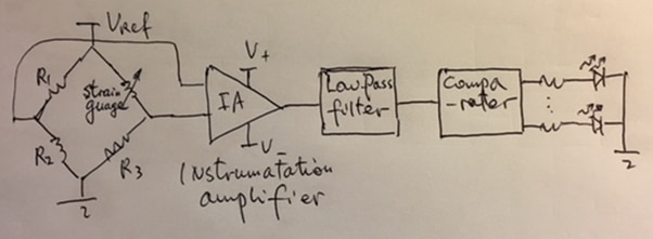
part 1 (is a force sensor interface with signal conditioning for a robot hand):
instrumentation amp of IN126, Low pass filter (20Hz) for noise, comparators (using LM324) for force levels 0, 20%, 40%, 60% and 80%.
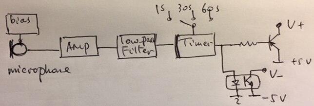
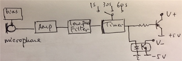
part 2 (is a "sound wake-up robot"; creating a module to activate a robot from sleep-mode for power saving via a sound ‘trigger’. ):
powered by 12v battery......
The sound trigger will switch on other parts of the robot circuits, which consumes a maximum of 2A continuously current.
The sound trigger shall be of the level of a normal human speaking voice at a distance of 1 metre. It will be desirable to arrange to reject frequencies outside of those intended for operation.
Once activated by the sound trigger, the robot shall be maintained in active mode for a pre-set period. The pre-set period shall be ‘factory selectable’ to a period of either 30 seconds or 60 seconds so that the robot will go to sleep mode again when there is no sound within the period. For testing, it would be advantageous to also select a time period of 2 seconds.
just have no idea of what an exact circuit would look like for both parts