


Hello all,
I am using two Xbee S2 modules to remotely sample analog data from a potentiometer. Here is my configuration.
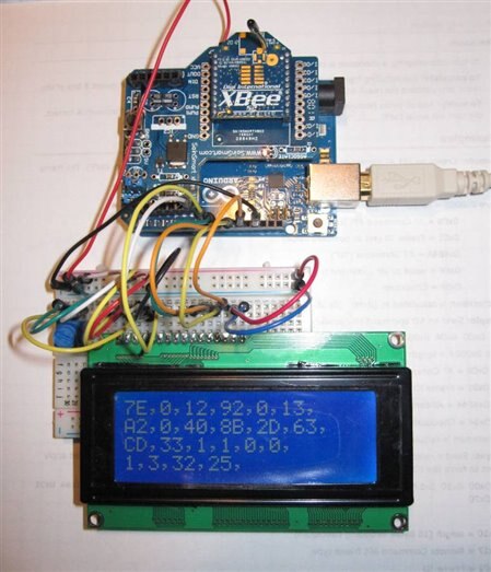
The local Xbee is mounted to an Xbee shield on an Arduino Uno.
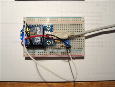
The remote Xbee has a potentiometer feeding voltage (0 to 1.2V) to Analog Input Zero on the Xbee (pin 20.) The USB cable is just for 5V power.
The code is listed below. The problem is that many of the data frames (frame type 0x92) that I get back from the remote are corrupted or otherwise wrong. I can use the checksum to drop the bogus frames on the floor, but they do make up about 50% of the frames I receive. Are other frames being sent by the remote Xbee, i.e. status or error frames, or something else? Is this normal?
The local XBee (coordinator) is programmed separately in API mode; the remote XBee is programmed separately in Transparent mode (AT commands.) Since I do get occasional correct frames of data, I think the XBees are programmed correctly
When I do get a good frame, the data in it is correct as you can see in the first picture [Ref. 2, pg. 114].
Can anyone help me out with this?
Thanks,
Kevin H.
References:
1. Building Wireless Sensor Networks: with ZigBee, XBee, Arduino, and Processing, Robert Faludi, O'Reilly Press, 2010.
2. XBee/XBee-Pro ZB RF Modules, Data Sheet, Digi International, Inc, November 2010.
Here is my code:
/*
This sketch reads ADI0 from the remote Xbee using a local (coordinator)
Xbee. The input to the remote ADI0 is a potentiometer set from 0 to 1.2V
Kevin Hartnett, April 2013
Based on sample code from Building Wireless Networks: with Zigbee, Xbee,
Arduino, and Processing, Robert Faludi, O'Reilly Press, 2010.
*** CONFIGURATION ***
SENDER: (REMOTE SENSOR RADIO)
ATID3456 (PAN ID)
ATDH -> set to SH of partner radio
ATDL -> set to SL of partner radio
ATJV1 -> rejoin with coordinator on startup
ATD02 pin 0 in analog in mode
ATIR64 sample rate 100 millisecs (hex 64)
* THE LOCAL RADIO _MUST_ BE IN API MODE *
RECEIVER: (LOCAL RADIO)
ATID3456 (PAN ID)
ATDH -> set to SH of partner radio
ATDL -> set to SL of partner radio
*/
#include <LiquidCrystal.h>
LiquidCrystal lcd(7,8,9,10,11,12);
int debugLED = 13;
int analogValue = 0;
byte dataArray[40]; //set aside 40 bytes for data from sending unit
int length;
int i;
byte chksum;
void setup() {
pinMode(debugLED, OUTPUT);
Serial.begin(9600);
lcd.begin(20, 4);
lcd.clear();
lcd.setCursor(0, 0);
}
void loop() {
// make sure everything we need is in the buffer
if (Serial.available() >= 21) {
// look for the start byte
dataArray[0] = Serial.read();
if (dataArray[0] == 0x7E) {
//blink debug LED to indicate when data is received
digitalWrite(debugLED, HIGH);
delay(10);
digitalWrite(debugLED, LOW);
//get length
dataArray[1] = Serial.read(); //read msb of length
dataArray[2] = Serial.read(); //read lsb of length
length = dataArray[1]*256 + dataArray[2];
dataArray[3] = Serial.read(); //read frame type
if(dataArray[3] == 0x92){ //0x92 means I/O data sample frame
//read the rest of the buffer and calcutate checksum
chksum = dataArray[3]; //begin checksum with frame type
for (i = 4; i <= length+3; i++) {
dataArray[i] = Serial.read();
chksum = chksum + dataArray[i]; //add to checksum
}
chksum = 0xFF - chksum; //should equal zero if data is good
//print dataArray to lcd if chksum == 0
if (!chksum){ //if chksum result is zero, continue
analogValue = dataArray[19]*256 + dataArray[20];
lcd.clear();
lcd.setCursor(0,0);
//lcd.print(chksum, HEX); //for debug
for (int k = 0; k <= length+3; k++){
if(k == 6) {lcd.setCursor(0,1);}
if(k == 12) {lcd.setCursor(0,2);}
if(k == 18) {lcd.setCursor(0,3);}
lcd.print(dataArray[k], HEX);
lcd.print(",");
}
}
}
delay(2000); //slow things down so you can read displayed data
}
}
}


