element14 Community
element14 Community
    Register Log In
  • Site
  • Search
  • Log In Register
  • About Us
  • Community Hub
    Community Hub
    • What's New on element14
    • Feedback and Support
    • Benefits of Membership
    • Personal Blogs
    • Members Area
    • Achievement Levels
  • Learn
    Learn
    • Ask an Expert
    • eBooks
    • element14 presents
    • Learning Center
    • Tech Spotlight
    • STEM Academy
    • Webinars, Training and Events
    • Learning Groups
  • Technologies
    Technologies
    • 3D Printing
    • FPGA
    • Industrial Automation
    • Internet of Things
    • Power & Energy
    • Sensors
    • Technology Groups
  • Challenges & Projects
    Challenges & Projects
    • Design Challenges
    • element14 presents Projects
    • Project14
    • Arduino Projects
    • Raspberry Pi Projects
    • Project Groups
  • Products
    Products
    • Arduino
    • Avnet Boards Community
    • Dev Tools
    • Manufacturers
    • Multicomp Pro
    • Product Groups
    • Raspberry Pi
    • RoadTests & Reviews
  • Store
    Store
    • Visit Your Store
    • Choose another store...
      • Europe
      •  Austria (German)
      •  Belgium (Dutch, French)
      •  Bulgaria (Bulgarian)
      •  Czech Republic (Czech)
      •  Denmark (Danish)
      •  Estonia (Estonian)
      •  Finland (Finnish)
      •  France (French)
      •  Germany (German)
      •  Hungary (Hungarian)
      •  Ireland
      •  Israel
      •  Italy (Italian)
      •  Latvia (Latvian)
      •  
      •  Lithuania (Lithuanian)
      •  Netherlands (Dutch)
      •  Norway (Norwegian)
      •  Poland (Polish)
      •  Portugal (Portuguese)
      •  Romania (Romanian)
      •  Russia (Russian)
      •  Slovakia (Slovak)
      •  Slovenia (Slovenian)
      •  Spain (Spanish)
      •  Sweden (Swedish)
      •  Switzerland(German, French)
      •  Turkey (Turkish)
      •  United Kingdom
      • Asia Pacific
      •  Australia
      •  China
      •  Hong Kong
      •  India
      •  Korea (Korean)
      •  Malaysia
      •  New Zealand
      •  Philippines
      •  Singapore
      •  Taiwan
      •  Thailand (Thai)
      • Americas
      •  Brazil (Portuguese)
      •  Canada
      •  Mexico (Spanish)
      •  United States
      Can't find the country/region you're looking for? Visit our export site or find a local distributor.
  • Translate
  • Profile
  • Settings
Arduino
  • Products
  • More
Arduino
Arduino Forum What is your go to DC motor driver for Arduino projects
  • Blog
  • Forum
  • Documents
  • Quiz
  • Events
  • Polls
  • Files
  • Members
  • Mentions
  • Sub-Groups
  • Tags
  • More
  • Cancel
  • New
Join Arduino to participate - click to join for free!
Actions
  • Share
  • More
  • Cancel
Forum Thread Details
  • Replies 28 replies
  • Subscribers 386 subscribers
  • Views 5076 views
  • Users 0 members are here
  • motor control
  • arduino
Related

What is your go to DC motor driver for Arduino projects

colporteur
colporteur over 2 years ago

My post  Raising the Bridge...Automation with Arduino: Failure reconciliation  details some of my failures with the L293N & L298N motor drivers.

Now I find myself looking for another DC motor driver. What DC motor driver do you use in Arduino projects? Why is it you motor driver of choice? Is there a Arduino library for the module or do you roll your own.

  • Sign in to reply
  • Cancel

Top Replies

  • shabaz
    shabaz over 1 year ago +3
    Another advantage of trying something new: Although I initially searched around for a reliable H-bridge to help colporteur it ended up helping me too. It turned out to make a nice little AC driver for…
  • shabaz
    shabaz over 1 year ago +2
    I don't know if I ever posted a photo of it, but that H450 driver (which was described here: Using H450 (Toshiba TB67H450) Motor Driver Boards with Arduino ) PCB arrived a while back. It appears to work…
  • shabaz
    shabaz over 1 year ago in reply to colporteur +2
    Hi Sean, The KiCad files, and the zip Arduino library file are here: https://github.com/shabaz123/h450 If you download that repository, then the KiCad project is in the motor_pcb folder. It is a KiCad…
Parents
  • shabaz
    shabaz over 1 year ago

    I don't know if I ever posted a photo of it, but that H450 driver (which was described here:   Using H450 (Toshiba TB67H450) Motor Driver Boards with Arduino   ) PCB arrived a while back. 

    It appears to work fine, can be screwed on top of an Arduino if mounting pillars are available and uses jumper wires to connect to the Arduino. The Arduino library for it that was described at that blog post works fine too. I think it will be more reliable that the L293/298 boards.

    In the photo below it was being used not as a motor driver, but for testing inductors, that big resistor was to limit current. Handy to have a H-bridge for various testing purposes.

    image

    • Cancel
    • Vote Up +2 Vote Down
    • Sign in to reply
    • Cancel
Reply
  • shabaz
    shabaz over 1 year ago

    I don't know if I ever posted a photo of it, but that H450 driver (which was described here:   Using H450 (Toshiba TB67H450) Motor Driver Boards with Arduino   ) PCB arrived a while back. 

    It appears to work fine, can be screwed on top of an Arduino if mounting pillars are available and uses jumper wires to connect to the Arduino. The Arduino library for it that was described at that blog post works fine too. I think it will be more reliable that the L293/298 boards.

    In the photo below it was being used not as a motor driver, but for testing inductors, that big resistor was to limit current. Handy to have a H-bridge for various testing purposes.

    image

    • Cancel
    • Vote Up +2 Vote Down
    • Sign in to reply
    • Cancel
Children
  • colporteur
    colporteur over 1 year ago in reply to shabaz

    Always impressed shabaz! It looks like you have done the heavy lift for me in that you have developed a PCB. I purchased some of the modules you mentioned but have never gotten around to board development.

    I'm planning a PCB board purchase shortly. Any chance I can get the KiCAD bits to generate the boards? What did you use as an Arduino driver?

    • Cancel
    • Vote Up 0 Vote Down
    • Sign in to reply
    • Cancel
  • shabaz
    shabaz over 1 year ago in reply to colporteur

    Hi Sean,

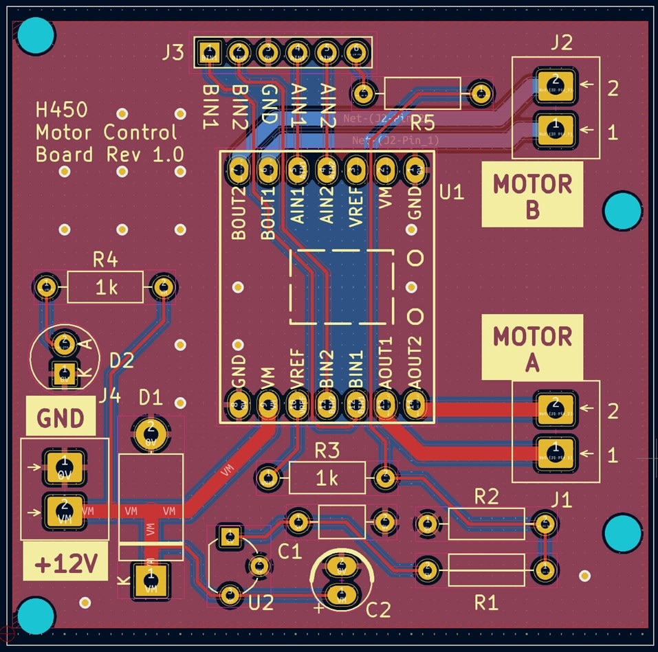
    The KiCad files, and the zip Arduino library file are here: https://github.com/shabaz123/h450

    If you download that repository, then the KiCad project is in the motor_pcb folder. It is a KiCad 7 project.

    There is also a zip file of Gerbers in the same folder, if you just want to order an identical PCB. 

    The Arduino library is called Motor450_library-1.0.0.zip

    image

    • Cancel
    • Vote Up +2 Vote Down
    • Sign in to reply
    • Cancel
  • colporteur
    colporteur over 1 year ago in reply to shabaz

    Your efficiency is troubling. Now I have to find time to fit this in. You couldn't have given me a week before responding:) I have a PCB board order going in shortly so it is timely I seen your message. Much appreciate the share.

    • Cancel
    • Vote Up +2 Vote Down
    • Sign in to reply
    • Cancel
  • colporteur
    colporteur over 1 year ago in reply to colporteur

    I'm hoping that you will indulge me in answering some questions about your design.

    After reviewing the schematic, I had a bunch of "I wonder why he did that?" type questions alone with "How did you do that?" questions.

    I recognize it is short comings in my ageing electronics knowledge and experience with KiCad . I'm looking to cheat and copy the answer from your test and avoid having to go back to school.

    I can open a new post or list the questions here, if you are willing.

    • Cancel
    • Vote Up 0 Vote Down
    • Sign in to reply
    • Cancel
  • shabaz
    shabaz over 1 year ago in reply to colporteur

    Hi Sean,

    Sure, it may be better at the following link though, if it's connected to that board:

     Using H450 (Toshiba TB67H450) Motor Driver Boards with Arduino 

    But I don't mind if it's here or a new post. If I can see it and know the answer, then I'll reply if I can.

    • Cancel
    • Vote Up 0 Vote Down
    • Sign in to reply
    • Cancel
  • colporteur
    colporteur over 1 year ago in reply to shabaz

    image

    I figured I would pop up the schematic to save people having to invest resources if they just wanted to follow along.

    1. Why D1? I've used diodes in series to prevent revering the polarity but why the 18V zenor?

    2. Why VM designation? It doesn't appear in defaults. How was it made?

    3. Why 0V and not a standard ground symbol?

    4. Why R3? I think you have described this before but I can't find notes.

    5. Why the "Do Not Fit"? You have some expansion ideas you left room for?

    • Cancel
    • Vote Up 0 Vote Down
    • Sign in to reply
    • Cancel
  • shabaz
    shabaz over 1 year ago in reply to colporteur

    Hi Sean,

    1. Since you're running the circuit along long lengths of track, you may have issues with inductive spikes, which could destroy circuitry. The diode is to try to clamp the voltage to a level that won't damage things. 

    2. VM just means the motor power supply, i.e. the supply that the H-bridge will use to drive the motor. So, if the motors use 12V, then VM is a 12V supply. It was created by using the Symbol Editor from the KiCad main window. I copied any existing power symbol (e.g. +5V symbol) into a user symbol library, and edited the text to be VM instead of +5V. This is my normal method for making any component schematic symbol; I try to find any symbol that is similar, and copy it into a user library and edit it and save it under a new symbol name. Sometimes I might start a symbol from scratch, but often it is easier to look for the closest one and copy it. 

    The general procedure for copying and modifying symbols in this way is shown in the screenshots below, but it is described in detail in the video here: https://www.youtube.com/watch?v=5Be7XOMmPQE&t=509s  at time 8mins 29 seconds.

    image

    3. Personal preference. I don't like using the ground symbol for what isn't actually connected to physical ground. The negative end of a battery, or the black wire on a power supply, is 0V as far as I'm concerned. The negative of a battery or the black wire is not electrically connected to ground.

    4. I can't remember the reason either now. I think it was just for some flexibility. Those resistors and wire links in that area can be used to redirect the VREF connection to a pin header if desired, to remotely adjust the current limit to the motor driver.

    5. This is just for some flexibility, since another user might want a different VREF value, and they can easily do it by replacing the wire links and the DNF with resistors acting as a potential divider, to supply a voltage lower than 5V to the VREF pin.

    • Cancel
    • Vote Up 0 Vote Down
    • Sign in to reply
    • Cancel
  • colporteur
    colporteur over 1 year ago in reply to shabaz

    Well thank you shabaz! I didn't realize you board design was providing for the model train motor requirements. I have some boards on order and will keep you posted on the testing.

    • Cancel
    • Vote Up +1 Vote Down
    • Sign in to reply
    • Cancel
  • colporteur
    colporteur over 1 year ago in reply to shabaz

    Are you willing to share the sym and mod file for the actual module?

    I would like to incorporate your layout into a bigger PCB. I looked through the link and didn't find the schematic symbol library or the footprint. I was hoping you might share.

    • Cancel
    • Vote Up 0 Vote Down
    • Sign in to reply
    • Cancel
  • shabaz
    shabaz over 1 year ago in reply to colporteur

    This is easy to do directly from the files you already have, by first selecting and then right-clicking on the module.

    As in the screenshot below, right-clicking on the module in the PCB, and selecting "Open in Footprint Editor"

    image

    Once you select that, the module will appear in the Footprint Editor, then you can simply click on File->Save As.

    When you do that, you'll see the following window appear. Choose your destination library. You don't need to create a new library for each new footprint. You can just create a single one called whatever you like, (say) User Global Footprint Library or whatever, and throw all your custom footprints into it if desired. If you don't currently have your own library, then create it by clicking on New Library and select Global and give it a name.

    image

    You can do all of the above with the schematic symbol too. Click to select, and then right-click on the module symbol, and select "Edit with Symbol Editor" and then do everything the same as above.

    I rarely create a separate sym or mod file. I just throw all new symbols and footprints into a single user global symbol library or user global footprint library. One day I might need to create a new library, but for now mine already has hundreds of custom footprints inside it, no problem at all. Often I will copy a footprint from a different library into my user one, and then make some tweaks to it. For instance in the screenshot below, you can see I have a footprint for a switch. I'm sure that already existed in a KiCad library, but I may have changed the size of the drill holes or the silkscreen or something, and I wanted my own variation, so I placed it in my User Global Footprint Library.

    For those more organized than me, they might create (say) a User Global Switch Footprint Library or whatever. 

    image

    • Cancel
    • Vote Up +1 Vote Down
    • Sign in to reply
    • Cancel
element14 Community

element14 is the first online community specifically for engineers. Connect with your peers and get expert answers to your questions.

  • Members
  • Learn
  • Technologies
  • Challenges & Projects
  • Products
  • Store
  • About Us
  • Feedback & Support
  • FAQs
  • Terms of Use
  • Privacy Policy
  • Legal and Copyright Notices
  • Sitemap
  • Cookies

An Avnet Company © 2025 Premier Farnell Limited. All Rights Reserved.

Premier Farnell Ltd, registered in England and Wales (no 00876412), registered office: Farnell House, Forge Lane, Leeds LS12 2NE.

ICP 备案号 10220084.

Follow element14

  • X
  • Facebook
  • linkedin
  • YouTube