element14 Community
element14 Community
    Register Log In
  • Site
  • Search
  • Log In Register
  • About Us
  • Community Hub
    Community Hub
    • What's New on element14
    • Feedback and Support
    • Benefits of Membership
    • Personal Blogs
    • Members Area
    • Achievement Levels
  • Learn
    Learn
    • Ask an Expert
    • eBooks
    • element14 presents
    • Learning Center
    • Tech Spotlight
    • STEM Academy
    • Webinars, Training and Events
    • Learning Groups
  • Technologies
    Technologies
    • 3D Printing
    • FPGA
    • Industrial Automation
    • Internet of Things
    • Power & Energy
    • Sensors
    • Technology Groups
  • Challenges & Projects
    Challenges & Projects
    • Design Challenges
    • element14 presents Projects
    • Project14
    • Arduino Projects
    • Raspberry Pi Projects
    • Project Groups
  • Products
    Products
    • Arduino
    • Avnet Boards Community
    • Dev Tools
    • Manufacturers
    • Multicomp Pro
    • Product Groups
    • Raspberry Pi
    • RoadTests & Reviews
  • Store
    Store
    • Visit Your Store
    • Choose another store...
      • Europe
      •  Austria (German)
      •  Belgium (Dutch, French)
      •  Bulgaria (Bulgarian)
      •  Czech Republic (Czech)
      •  Denmark (Danish)
      •  Estonia (Estonian)
      •  Finland (Finnish)
      •  France (French)
      •  Germany (German)
      •  Hungary (Hungarian)
      •  Ireland
      •  Israel
      •  Italy (Italian)
      •  Latvia (Latvian)
      •  
      •  Lithuania (Lithuanian)
      •  Netherlands (Dutch)
      •  Norway (Norwegian)
      •  Poland (Polish)
      •  Portugal (Portuguese)
      •  Romania (Romanian)
      •  Russia (Russian)
      •  Slovakia (Slovak)
      •  Slovenia (Slovenian)
      •  Spain (Spanish)
      •  Sweden (Swedish)
      •  Switzerland(German, French)
      •  Turkey (Turkish)
      •  United Kingdom
      • Asia Pacific
      •  Australia
      •  China
      •  Hong Kong
      •  India
      •  Korea (Korean)
      •  Malaysia
      •  New Zealand
      •  Philippines
      •  Singapore
      •  Taiwan
      •  Thailand (Thai)
      • Americas
      •  Brazil (Portuguese)
      •  Canada
      •  Mexico (Spanish)
      •  United States
      Can't find the country/region you're looking for? Visit our export site or find a local distributor.
  • Translate
  • Profile
  • Settings
Arduino
  • Products
  • More
Arduino
Arduino Forum Can Someone Review my Schematic for Android GPIO?
  • Blog
  • Forum
  • Documents
  • Quiz
  • Events
  • Polls
  • Files
  • Members
  • Mentions
  • Sub-Groups
  • Tags
  • More
  • Cancel
  • New
Join Arduino to participate - click to join for free!
Actions
  • Share
  • More
  • Cancel
Forum Thread Details
  • State Not Answered
  • Replies 7 replies
  • Subscribers 386 subscribers
  • Views 1225 views
  • Users 0 members are here
  • android
  • arduino nano
  • mcp2200
  • arduino
Related

Can Someone Review my Schematic for Android GPIO?

mjones517
mjones517 9 months ago

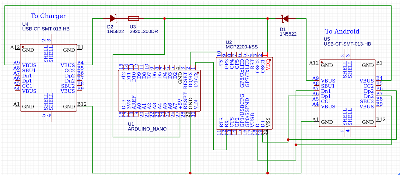
Okay, so I want to access Arduino GPIO pins via Android. My plan is to access them via a serial connection using an MCP2200. I can read / write to the serial port on Android, which can then interact with the Arduino.

The problem is I also want to be able to plug in the phone and have it charging while still being able to access the Arduino. I came up with this, but am pretty new to the electronics side of things and want to avoid blowing things up. Will this do what I want?

It's essentially two USB ports. One goes to the charger, the other to the phone. The Arduino and MCP2200 sit in the middle.

image

  • Sign in to reply
  • Cancel

Top Replies

  • wolfgangfriedrich
    wolfgangfriedrich 9 months ago +2
    Short answer is: No this will not work in the current form. Long answer: The basics: Connect all GND pins on both USB connectors, Arduino+ VSS and a schematic GND symbol Connect all VBUS on both…
  • shabaz
    shabaz 9 months ago +2
    Hi, I agree with everything Wolfgang mentioned. If you want to make life easier, it is possible for a few $ to obtain a ready-made USB OTG cable with extra port for charging. It will contain the electronics…
  • wolfgangfriedrich
    wolfgangfriedrich 9 months ago in reply to mjones517 +2
    I agree with everything shabaz mentioned. But if you want to go the fun route and design your own solution,here we go. Even as a USB device you need the 12 MHz crystal. The chip needs some sort of…
  • wolfgangfriedrich
    0 wolfgangfriedrich 9 months ago

    Short answer is: No this will not work in the current form.

    Long answer:

    The basics:

    Connect all GND pins on both USB connectors, Arduino+ VSS and a schematic GND symbol

    Connect all VBUS on both connectors + all pins that need +5V.

    Connect all SHELL on both connectors together.

    U2: read the whole datasheet, OSC1,2 need a 12 MHz crystal with load capacitors. Rst needs a resistor to vbus, capacitor to gnd. Add 100nF capacitors to all power pins.

    Now it gets complicated. If you connect CC1,2 on both USB connectors and the charger and Android speak USB PD, VBUS could be up to 20V and blow everything up. To avoid that you add 2 x 5.1 KOhm resistors to GND on 5he charger CC1,2 pins. This limits the charger to 5V, max 3A.

    I am not sure what you want to achieve with the diodes+ fuse.

    Did you make sure the Android device can be a USB host?

    Hint: turn U1 and U2 90deg CCW. Schematics are much easier to read when symbol pins are left and right. Add netnames to all signals, it helps a lot during layout.

    • Cancel
    • Vote Up +2 Vote Down
    • Sign in to reply
    • Verify Answer
    • Cancel
  • mjones517
    0 mjones517 9 months ago in reply to wolfgangfriedrich

    First off, thank you for replying!

    A few clarifying questions.

    I am using none of the USB host features of the MCP2200. I'm only using the UART capability. I want to send serial commands, which I can then use to control the Arduino GPIO.

    If I could use the MCP2200 as a USB device I wouldn't need the Arduino. There's GPIO on the chip.

    So since I'm not using OSC1/2, do I still need the crystal?

    Also... The Schokkey diodes and fuse are to try and prevent the power from the battery from back flowing into the charger.

    • Cancel
    • Vote Up 0 Vote Down
    • Sign in to reply
    • Verify Answer
    • Cancel
  • shabaz
    0 shabaz 9 months ago

    Hi,

    I agree with everything Wolfgang mentioned.

    If you want to make life easier, it is possible for a few $ to obtain a ready-made USB OTG cable with extra port for charging. It will contain the electronics to ensure the type A port doesn't see excessive voltage.

    Similarly, you could use a ready-made USB-UART board or adapter to plug into that type A port.

    image

    • Cancel
    • Vote Up +2 Vote Down
    • Sign in to reply
    • Verify Answer
    • Cancel
  • wolfgangfriedrich
    0 wolfgangfriedrich 9 months ago in reply to mjones517

    I agree with everything shabaz mentioned. 

    But if you want to go the fun route and design your own solution,here we go.

    Even as a USB device you need the 12 MHz crystal. The chip needs some sort of timing reference.

    The diodes are not needed,just think what would happen if you plug the charger straight into the phone. Thinking

    Ask away, we are here to help. 

    • Cancel
    • Vote Up +2 Vote Down
    • Sign in to reply
    • Verify Answer
    • Cancel
  • mjones517
    0 mjones517 9 months ago

    Today was interesting and I've learned some stuff.

    I decided step 1 was just getting the MCP2200 to register as a serial device. I could not get this to work for the life of me, not even on my laptop. I suspect wolfgangfriedrich is correct and I need to add the 12 Mhz crystal. I don't have one, so I can't test for sure.

    Out of frustration I plugged my Arduino directly into my Pixel 6 and opened a serial monitor app. I was able to directly connect, no intermediate chip required. I even got an LED to turn on / off.

    I think the solution I'm going to take is to do that and also buy the USB OTG cable shabaz suggested. That will accomplish everything I need to make this project work.

    My last project used a Raspberry Pi. I realized at the end the only thing I needed the Pi for was GPIO, and that the rest of the project would have been cheaper / easier if I could have just used an Android tablet. Now that I know I can control an Arduino using serial commands, I can skip the bloodbath of trying to find / use a Pi.

    Thanks again for everyone's help! As you've figured out I'm a raw newbie.

    • Cancel
    • Vote Up +2 Vote Down
    • Sign in to reply
    • Verify Answer
    • Cancel
  • wolfgangfriedrich
    0 wolfgangfriedrich 9 months ago in reply to mjones517

    Thanks for reporting back, mjones517 . Awesome to hear that you found a solution, that is even more elegant than what we have suggested to you. Getting to blinky is always a huge step. You are less of a newbie now, the bag of experience is filling up. Well done.

    Good luck with your project.

    • Cancel
    • Vote Up 0 Vote Down
    • Sign in to reply
    • Verify Answer
    • Cancel
  • James_Smith
    0 James_Smith 8 months ago

    I am a newbie and reviewed your schematic. I have some points about your project. Correct me if I am wrong:

    The grounds of the MCP2200 (U2) and the Arduino Nano (U1) are properly connected, which is good. But if the USB ports don't share a ground, the phone might have trouble talking to the MCP2200, and it could also have issues charging.
    In any electric circuit, ground (GND) acts like a shared reference for voltages. If the grounds are separated:

    - Serial communication can fail because the signal lines (TX/RX) need a common voltage to function correctly.
    - Powering the phone might be inconsistent or could completely stop working.

    Beside this, Your circuit is well thought out for someone new to electronics, and it should work fine for charging and serial communication. Test the setup with a multimeter to confirm proper voltages and current flow. Slight smile

    • Cancel
    • Vote Up 0 Vote Down
    • Sign in to reply
    • Verify Answer
    • Cancel
element14 Community

element14 is the first online community specifically for engineers. Connect with your peers and get expert answers to your questions.

  • Members
  • Learn
  • Technologies
  • Challenges & Projects
  • Products
  • Store
  • About Us
  • Feedback & Support
  • FAQs
  • Terms of Use
  • Privacy Policy
  • Legal and Copyright Notices
  • Sitemap
  • Cookies

An Avnet Company © 2025 Premier Farnell Limited. All Rights Reserved.

Premier Farnell Ltd, registered in England and Wales (no 00876412), registered office: Farnell House, Forge Lane, Leeds LS12 2NE.

ICP 备案号 10220084.

Follow element14

  • X
  • Facebook
  • linkedin
  • YouTube