element14 Community
element14 Community
    Register Log In
  • Site
  • Search
  • Log In Register
  • About Us
  • Community Hub
    Community Hub
    • What's New on element14
    • Feedback and Support
    • Benefits of Membership
    • Personal Blogs
    • Members Area
    • Achievement Levels
  • Learn
    Learn
    • Ask an Expert
    • eBooks
    • element14 presents
    • Learning Center
    • Tech Spotlight
    • STEM Academy
    • Webinars, Training and Events
    • Learning Groups
  • Technologies
    Technologies
    • 3D Printing
    • FPGA
    • Industrial Automation
    • Internet of Things
    • Power & Energy
    • Sensors
    • Technology Groups
  • Challenges & Projects
    Challenges & Projects
    • Design Challenges
    • element14 presents Projects
    • Project14
    • Arduino Projects
    • Raspberry Pi Projects
    • Project Groups
  • Products
    Products
    • Arduino
    • Avnet Boards Community
    • Dev Tools
    • Manufacturers
    • Multicomp Pro
    • Product Groups
    • Raspberry Pi
    • RoadTests & Reviews
  • Store
    Store
    • Visit Your Store
    • Choose another store...
      • Europe
      •  Austria (German)
      •  Belgium (Dutch, French)
      •  Bulgaria (Bulgarian)
      •  Czech Republic (Czech)
      •  Denmark (Danish)
      •  Estonia (Estonian)
      •  Finland (Finnish)
      •  France (French)
      •  Germany (German)
      •  Hungary (Hungarian)
      •  Ireland
      •  Israel
      •  Italy (Italian)
      •  Latvia (Latvian)
      •  
      •  Lithuania (Lithuanian)
      •  Netherlands (Dutch)
      •  Norway (Norwegian)
      •  Poland (Polish)
      •  Portugal (Portuguese)
      •  Romania (Romanian)
      •  Russia (Russian)
      •  Slovakia (Slovak)
      •  Slovenia (Slovenian)
      •  Spain (Spanish)
      •  Sweden (Swedish)
      •  Switzerland(German, French)
      •  Turkey (Turkish)
      •  United Kingdom
      • Asia Pacific
      •  Australia
      •  China
      •  Hong Kong
      •  India
      •  Korea (Korean)
      •  Malaysia
      •  New Zealand
      •  Philippines
      •  Singapore
      •  Taiwan
      •  Thailand (Thai)
      • Americas
      •  Brazil (Portuguese)
      •  Canada
      •  Mexico (Spanish)
      •  United States
      Can't find the country/region you're looking for? Visit our export site or find a local distributor.
  • Translate
  • Profile
  • Settings
Arduino
  • Products
  • More
Arduino
Arduino Forum 16*2 LCD getting weird characters
  • Blog
  • Forum
  • Documents
  • Quiz
  • Events
  • Polls
  • Files
  • Members
  • Mentions
  • Sub-Groups
  • Tags
  • More
  • Cancel
  • New
Join Arduino to participate - click to join for free!
Actions
  • Share
  • More
  • Cancel
Forum Thread Details
  • Replies 34 replies
  • Subscribers 401 subscribers
  • Views 9693 views
  • Users 0 members are here
  • lcd
  • arduino
Related

16*2 LCD getting weird characters

jrcs
jrcs over 9 years ago

Hi all.


This is my first post so I hope it is at the right place.


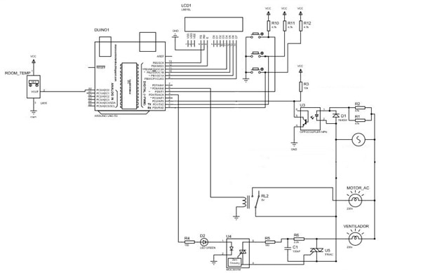
I'm working on a project whose objective is to control two ac loads (one ac fan, controlled by phase angle control and one ac motor controlled by a 5V relay) and output to an LCD the room temperature and the % of fan speed.


The code I wrote seem to work fine without the AC loads connected. I tested it for long periods of time (+12 hours) and everything is ok.


The problem is when I connect both (or just one) AC loads, I always end up with my LCD info corrupted like this:


image


https://1drv.ms/i/s!Ah12lhUG5VG8g9FOhR9Y0ccFTsq2Rg


Sometimes past 2 minutes, sometimes past 10 minutes... It's random but it always end up like this.


I'm guessing it's noise problems due to the loads switching TRIAC/Relay. The TRIAC its connected trough a optocoupler but the relay it's directly connected to the arduino.


First, I put the lcd.clear() function in my code to "rebuild" the info from time to time but it doesen't work 100% and it's not a "clean" solution for the pourpose.


The AC loads are connected to the grid but the arduino is powered from my computer's usb port. Already put an EMI filter into AC main input of my loads but no solution.


Is there a solution to this problem? Any help?

Sorry for my poor english but I'm a little bit rusty.


Regards

  • Sign in to reply
  • Cancel

Top Replies

  • niko.vicencio
    niko.vicencio over 8 years ago +3
    Hi I had the same problem, the lcd showed random characters when the electromechanical relay commutated. I solved this problem, changing the relay by a ssr (Solid state relay). I hope that my answer help…
  • WarrenW
    WarrenW over 9 years ago +2
    How are you driving the relay from the arduino? Direct off the micro or via a transistor? Does the relay have a snubber cap across the coil and a back emf diode? Does the arduino have a filter capacitor…
  • Robert Peter Oakes
    Robert Peter Oakes over 9 years ago +2
    Can you please provide a schematic of your setup and also a full picture (Cant see all your connections in the one provided. You can upload them right into this community post. I have done what your describing…
  • WarrenW
    WarrenW over 9 years ago

    How are you driving the relay from the arduino? Direct off the micro or via a transistor? Does the relay have a snubber cap across the coil and a back emf diode? Does the arduino have a filter capacitor near the supply rails?

    All things to look for to prevent the back emf.


    Also you may be getting induced noise in your supply from the triac switching, again check for supply noise with a scope perhaps?


    HTH

    Warren.

    • Cancel
    • Vote Up +2 Vote Down
    • Sign in to reply
    • Cancel
  • jrcs
    jrcs over 9 years ago in reply to WarrenW

    Hi sir,


    I don't have a scope (and that's a problem, I know).


    The relay is a module (SRD-05VDC) and yes, it's being driven directly from the arduino.

    No filter near the supply rails. You mean a cap through vcc and gnd supply right?


    I'll try to get my hands on a scope in the next few days.


    Regards.

    • Cancel
    • Vote Up 0 Vote Down
    • Sign in to reply
    • Cancel
  • Robert Peter Oakes
    Robert Peter Oakes over 9 years ago

    Can you please provide a schematic of your setup and also a full picture (Cant see all your connections in the one provided. You can upload them right into this community post.


    I have done what your describing on several occasions and not run into mains based issues so this is why I am interested to se how everything is wired


    You should not need a scope to fix this and if the LCD is connected as I think it is, then the scope will not help a lot.

    Thanks

    • Cancel
    • Vote Up +2 Vote Down
    • Sign in to reply
    • Cancel
  • mcb1
    mcb1 over 9 years ago in reply to Robert Peter Oakes

    Also

    If the LCD gets corrupted it really needs a power reset.

    There is no reset pin on the controller in these displays.


    As Peter has suggested a schematic of how you've connected the relay and more importantly how you drive the relay (turn it on/off) will help with the answer.


    Thanks

    Mark

    • Cancel
    • Vote Up 0 Vote Down
    • Sign in to reply
    • Cancel
  • Gough Lui
    Gough Lui over 9 years ago

    What is your setup? It appears maybe you have some inducted noise interfering with communications from the board. Maybe you have long LCD bus lines which are more prone to picking up interference from the AC mains, which you should re-route, shorten, or maybe even use shielded cable. Perhaps try isolating the relay power supply lines from the LCD lines by having separate ground wires (in the case you've commoned them up on a breadboard in a "bus" fashion). I would also suggest increasing the separation between a phase control device and the arduino, as many of those devices have high in-rush currents when "cutting in", and this can result in significant EMF generation. Another possibility is that you might have short voltage dips when switching your phase-control dimmer (information might be necessary), so perhaps try thicker Vcc/GND leads to the display and bypassing the supply with a sizeable ceramic/MKT polyester + electrolytic capacitor at the display itself could help.


    - Gough

    • Cancel
    • Vote Up +1 Vote Down
    • Sign in to reply
    • Cancel
  • dougw
    dougw over 9 years ago

    It sounds like your arduino is not crashing, just the display is getting corrupted data.

    You can try checking the clocking signals to the display - make sure they are low impedance connections not running close to high voltage AC wires.

    Try disconnecting the clocking signals and grounding the display clocks at the display to confirm everything else is running properly and no random characters get clocked into the display. If random characters still show up, then the power supply to the display becomes the next most likely issue - put a large capacitor across the display power supply. Try moving the AC parts of your circuit further away from the digital parts.

    • Cancel
    • Vote Up 0 Vote Down
    • Sign in to reply
    • Cancel
  • clem57
    clem57 over 9 years ago

    I would go so far as having the breadboard for the LCD diferent from the one for the higher voltage.

    clem

    • Cancel
    • Vote Up 0 Vote Down
    • Sign in to reply
    • Cancel
  • jrcs
    jrcs over 9 years ago

    Hi all,


    Thank you all for your time.


    I took a picture today of the system today. It's not very "clean" but I was really short on time to test it. You can see it here: https://1drv.ms/i/s!Ah12lhUG5VG8g9FU0eNo8CpDdW1WYQ  I'll try to post the schematic later today when I arrive home.


    I have done some measurements with a scope with a borrowed scope. The 5V supply is getting lots of spikes when I open or close the relay (more when I close it so I only took pictures of closing).


    This is what I measure: https://1drv.ms/i/s!Ah12lhUG5VG8g9FRBvXyADPi7U7WZQ


    Then I add 2x470uF capacitores to 5V: https://1drv.ms/i/s!Ah12lhUG5VG8g9FS6mhCWvuhGU6JZw


    Not very helpfull. So I was reading around and added a snubber in paralel with the motor to see if it gets any better: https://1drv.ms/i/s!Ah12lhUG5VG8g9FTdvyVX-heJbancA


    So, basically I think the problem is the coil on the relay that is giving me all this spikes.


    I measured the system with the phase angle control and I get some noise at low firing angles but it doesn't seem to be enough for the problem... the noise is very low.


    Thank you all in advance.

    • Cancel
    • Vote Up +1 Vote Down
    • Sign in to reply
    • Cancel
  • jrcs
    jrcs over 9 years ago

    The schematic it's this but with arduino Mega.

    • Cancel
    • Vote Up 0 Vote Down
    • Sign in to reply
    • Cancel
  • jrcs
    jrcs over 9 years ago

    image

    • Cancel
    • Vote Up +1 Vote Down
    • Sign in to reply
    • Cancel
>
element14 Community

element14 is the first online community specifically for engineers. Connect with your peers and get expert answers to your questions.

  • Members
  • Learn
  • Technologies
  • Challenges & Projects
  • Products
  • Store
  • About Us
  • Feedback & Support
  • FAQs
  • Terms of Use
  • Privacy Policy
  • Legal and Copyright Notices
  • Sitemap
  • Cookies

An Avnet Company © 2025 Premier Farnell Limited. All Rights Reserved.

Premier Farnell Ltd, registered in England and Wales (no 00876412), registered office: Farnell House, Forge Lane, Leeds LS12 2NE.

ICP 备案号 10220084.

Follow element14

  • X
  • Facebook
  • linkedin
  • YouTube