element14 Community
element14 Community
    Register Log In
  • Site
  • Search
  • Log In Register
  • About Us
  • Community Hub
    Community Hub
    • What's New on element14
    • Feedback and Support
    • Benefits of Membership
    • Personal Blogs
    • Members Area
    • Achievement Levels
  • Learn
    Learn
    • Ask an Expert
    • eBooks
    • element14 presents
    • Learning Center
    • Tech Spotlight
    • STEM Academy
    • Webinars, Training and Events
    • Learning Groups
  • Technologies
    Technologies
    • 3D Printing
    • FPGA
    • Industrial Automation
    • Internet of Things
    • Power & Energy
    • Sensors
    • Technology Groups
  • Challenges & Projects
    Challenges & Projects
    • Design Challenges
    • element14 presents Projects
    • Project14
    • Arduino Projects
    • Raspberry Pi Projects
    • Project Groups
  • Products
    Products
    • Arduino
    • Avnet Boards Community
    • Dev Tools
    • Manufacturers
    • Multicomp Pro
    • Product Groups
    • Raspberry Pi
    • RoadTests & Reviews
  • Store
    Store
    • Visit Your Store
    • Choose another store...
      • Europe
      •  Austria (German)
      •  Belgium (Dutch, French)
      •  Bulgaria (Bulgarian)
      •  Czech Republic (Czech)
      •  Denmark (Danish)
      •  Estonia (Estonian)
      •  Finland (Finnish)
      •  France (French)
      •  Germany (German)
      •  Hungary (Hungarian)
      •  Ireland
      •  Israel
      •  Italy (Italian)
      •  Latvia (Latvian)
      •  
      •  Lithuania (Lithuanian)
      •  Netherlands (Dutch)
      •  Norway (Norwegian)
      •  Poland (Polish)
      •  Portugal (Portuguese)
      •  Romania (Romanian)
      •  Russia (Russian)
      •  Slovakia (Slovak)
      •  Slovenia (Slovenian)
      •  Spain (Spanish)
      •  Sweden (Swedish)
      •  Switzerland(German, French)
      •  Turkey (Turkish)
      •  United Kingdom
      • Asia Pacific
      •  Australia
      •  China
      •  Hong Kong
      •  India
      •  Korea (Korean)
      •  Malaysia
      •  New Zealand
      •  Philippines
      •  Singapore
      •  Taiwan
      •  Thailand (Thai)
      • Americas
      •  Brazil (Portuguese)
      •  Canada
      •  Mexico (Spanish)
      •  United States
      Can't find the country/region you're looking for? Visit our export site or find a local distributor.
  • Translate
  • Profile
  • Settings
Arduino
  • Products
  • More
Arduino
Arduino Forum FM Radio review
  • Blog
  • Forum
  • Documents
  • Quiz
  • Events
  • Polls
  • Files
  • Members
  • Mentions
  • Sub-Groups
  • Tags
  • More
  • Cancel
  • New
Join Arduino to participate - click to join for free!
Actions
  • Share
  • More
  • Cancel
Forum Thread Details
  • Replies 28 replies
  • Subscribers 393 subscribers
  • Views 4018 views
  • Users 0 members are here
  • fm radio
  • rotary_encoder
  • i2c lcd
  • speaker amplifier
  • arduino
Related

FM Radio review

hofa
hofa over 8 years ago

Hi everyone,


This is my first ever electronics project. I'm an IT infrastructure professional but as most of my kind, I only deal with servers, switches, routers, operating systems and so forth. I designed and breadboarded a simple fm radio with an Arduino UNO and I'm here to ask what I could improve before soldering everything together with an Arduino Nano.


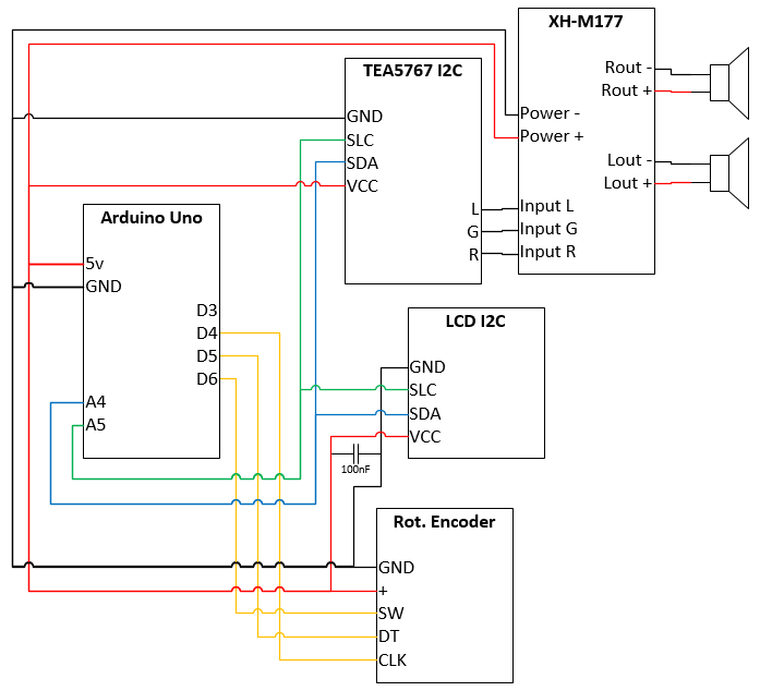
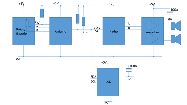
Components (is it correct to call these 'active components'?):

  • Aruino Uno (despite what the scheme says, planning the use a nano for the finished product)
  • TEA5767 on an I2C board
  • A 2x16 LCD connected through an I2C board
  • XH-M177 speaker amplifier (with to 8ohm 0,5 W speakers) with a volume knob (PotMeter) which clicks off when rotated all the way left.
  • Rotary encoder for tuning


Edit: new scheme after recomendations. I stated that a 100nF capacitor was enough for the LCD not to go haywire when clicking off the volume button... that was incorrect, switched it back to a 100uF (I don't have any others).

image


I added one capacitor because the LCD would go haywire when I switched off/on the amplifier. What do you guys think about this scheme? I am going to add a simple on/off switch to completely turn of the circuitry when not in use.


I tried catching the off switch from the amplifier but power still seems to go through after it clicked off. I found one pin that still produced around 1V (in stead of 5V) but I don't know how to use that because it's still letting current through and a digitalRead would not be able to catch the 'off' action, right?

Edit: wrong: The threshold is about 0.3*VCC (= 1.5V when VCC = 5V) so that's enough to catch it. Maybe I'll put a resistor in place to be more certain... Changed the code accordingly.


Also, I don't understand the concept around pull-down and pull-up resistors. I watched the latest TBHS (BB8 with LED art) and he speaks about it but it's all a bit too fast for me. I really do want to understand it.


The code as it is below, feel free to comment on this too (edited this too after being able to catch the volume knob off switch state):


//Libraries
#include <TEA5767.h>
#include <LiquidCrystal_I2C.h>
#include <MD_REncoder.h>
#include <EEPROM.h>

//I2C address 63 (0x3F) = Radio
//I2C address 96 (0x60) = LCD

//Constants
const int radioPin = 7;
const int ampReadPin = 2;
const int ampPowerPin = 3;
const int REclk = 4;
const int REdt = 5;
const int REsw = 6;
const boolean debug = false;
#define I2C_ADDR    0x3F

//Variables
double old_freq;
double temp_freq;
double freq;
boolean ampReadPower;
boolean ampReadPower_old;
int stereo;
int stereo_old;
int signal_level;
int signal_level_old;
int REdt_old;
int REdt_temp;
int REclk_temp;
unsigned char buf[5];
unsigned long ms;
boolean rotPot = true;
int slowDown = 30000;

//Signal chars
byte level1[8] = {0b00000,0b00000,0b00000,0b00000,0b00000,0b00000,0b00011,0b11111};
byte level2[8] = {0b00000,0b00000,0b00000,0b00000,0b00001,0b01111,0b11111,0b11111};
byte level3[8] = {0b00000,0b00000,0b00000,0b00111,0b11111,0b11111,0b11111,0b11111};
byte level4[8] = {0b00000,0b00011,0b11111,0b11111,0b11111,0b11111,0b11111,0b11111};
byte level5[8] = {0b01111,0b11111,0b11111,0b11111,0b11111,0b11111,0b11111,0b11111};
byte loading[8] = {0b00000,0b00000,0b00000,0b11111,0b11111,0b00000,0b00000,0b00000};

//I2C pinout SLC and SDA - Arduino pins A5 and A4
LiquidCrystal_I2C lcd(I2C_ADDR, 16, 2);
TEA5767 Radio;

// Rotary encoder
MD_REncoder R = MD_REncoder(4, 5);

void setup() {
  Serial.begin(57600);

  // Initiate rotary encoder
  R.begin();

  // Set amplifier pins
  pinMode(ampReadPin, INPUT);
  pinMode(ampPowerPin, OUTPUT);
  digitalWrite(ampPowerPin, LOW);

  // Set Rotary Encoder pins
  pinMode(REclk, INPUT);
  pinMode(REdt, INPUT);
  pinMode(REsw, INPUT);

  // Initiate LCD
  lcd.begin ();
  lcd.backlight();
  lcd.display();
  lcd.clear();
    
  // Set radio pin
  pinMode(radioPin, OUTPUT);
  digitalWrite(radioPin, HIGH);
  
  // Initiate Radio
  Radio.init();
  EEPROM.get(0, freq);
  Radio.set_frequency(freq);
  Radio.read_status(buf);
  stereo = Radio.stereo(buf);
  signal_level = Radio.signal_level(buf);
  
  // create signal characters
  lcd.createChar(1, level1);
  lcd.createChar(2, level2);
  lcd.createChar(3, level3);
  lcd.createChar(4, level4);
  lcd.createChar(5, level5);
  lcd.createChar(6, loading);

  // Display loading screen and boot amp
  loadingScreen(2200);
  digitalWrite(ampPowerPin, HIGH);
  delay(100);
  ampReadPower = digitalRead(ampReadPin);
  if (ampReadPower == LOW) setStandby(LOW);
  ampReadPower_old = ampReadPower;

  // First display showing
  displayFreq();
  displayStereo();
  displaySignal();
}

void loop() {
  // Read rotary encoder changes and update frequency
  uint8_t x = R.read();
  if (x) 
  {
    x == DIR_CW ? freq+=0.1 : freq-=0.1;
    if (freq < 87.5) freq = 87.5;
    if (freq > 108.0) freq = 108.0;
    Serial.println(freq);
  }

  // Slow down screen updates to about once every second
  // This is needed for the Rotary encoder to work
  if ((slowDown += 1) > 30000) {

    // Soft poweroff by reading amp power status
    ampReadPower = digitalRead(ampReadPin);
    if (ampReadPower != ampReadPower_old) {
      ampReadPower_old = ampReadPower;
      setStandby(ampReadPower);
    }
    
    // Get Radio status
    Radio.read_status(buf);

    // Fill radio info
    stereo = Radio.stereo(buf);
    signal_level = Radio.signal_level(buf);
  
    // Only change display if 'stereo' changes
    if (stereo != stereo_old) {
      displayStereo();
      stereo_old = stereo;
    }
  
    // Only change display if 'signal' changes
    if (signal_level != signal_level_old) {
      displaySignal();
      signal_level_old = signal_level;
    }

    // Only change display and frequency if 'freq' changes
    if (freq != old_freq) {
      displayFreq();
  
      // Set timer for next block
      if (rotPot) {
        ms = millis();
        rotPot = false;
      }
  
      // Only change frequency if rotary encoder hasn't been changed in 500ms
      if (ms + 500 < millis() and temp_freq == freq) {
        Radio.set_frequency(freq);
        old_freq = freq;
        rotPot = true;
      }
      
      temp_freq = freq;

      // Write frequency to EEPROM
      EEPROM.put(0, freq);
    }
    
    slowDown = 0;
  }
}

/////////////////////////
//      FUNCTIONS      //
/////////////////////////

// Set standby state
void setStandby(int state) {
  if (state == HIGH) {
    // Disable amp so we don't get noise
    digitalWrite(ampPowerPin, LOW);
    // Enable display
    lcd.display();
    lcd.backlight();
    // enable radio
    digitalWrite(radioPin, state);
    Radio.set_frequency(freq);
    // give radio time to load
    loadingScreen(1400);
    displayFreq();
    // enable amp
    digitalWrite(ampPowerPin, HIGH);
  } else {
    // disable display
    lcd.clear();
    lcd.setCursor(0,0);
    lcd.print("Volume off...");
    delay(1000);
    lcd.noDisplay();
    lcd.noBacklight();
    // Disable radio
    digitalWrite(radioPin, state);
  }
  

}

// Display the wanted frequency
void displayFreq() {
  lcd.setCursor(0, 0);
  lcd.print("   ");
  if (freq < 100) {
    lcd.print(" ");
  }
  lcd.print(freq);
  lcd.print(" Mhz ");
}

// Display wether sound is in Stereo or Mono
void displayStereo() {
  lcd.setCursor(0, 1);
  if (stereo) lcd.print("Stereo");
  else lcd.print("Mono  ");
}

// Display the signal strength
void displaySignal() {
  lcd.setCursor(11, 1);
  signal_level >= 2 ? lcd.write((byte) 1) : lcd.print(" ");
  signal_level >= 4 ? lcd.write((byte) 2) : lcd.print(" ");
  signal_level >= 6 ? lcd.write((byte) 3) : lcd.print(" ");
  signal_level >= 8 ? lcd.write((byte) 4) : lcd.print(" ");
  signal_level >= 10 ? lcd.write((byte) 5) : lcd.print(" ");
}

// Clear 'old' LCD values to force an update
void clearLCDValues() {
  double old_freq;
  int stereo_old;
  int signal_level_old;  
}

void loadingScreen(int loadDelay) {
  // Wait for sound till radio module inits completely + show loading
  lcd.clear();
  lcd.setCursor(0,0);
  lcd.print("   Loading...   ");
  lcd.setCursor(0,1);
  for(int x=0 ; x<16 ; x++) {
    //lcd.print("-");
    lcd.write((byte) 6);
    delay((double) loadDelay/16);
  }
  lcd.clear();
}


Thank you very much for your time!


Best regards,

Thomas


Message was edited by: Thomas Hofkens changed up the scheme and code to reflect changes as proposed by others

  • Sign in to reply
  • Cancel

Top Replies

  • shabaz
    shabaz over 8 years ago +2
    Hi Thomas, The SDA and SCL lines specifically either need a resistor (try about 4.7k) to +5v, or they should be omitted if the Arduino already has them integrated. There should be no resistors to 0V, which…
  • Jan Cumps
    Jan Cumps over 8 years ago in reply to hofa +2
    Ok. The module already has the required resistors. They are R2 and R3 on your drawing. I had a more stable encoder when adding a few capacitors. It takes care that the operation isn't jumpy and nervous…
  • hofa
    hofa over 8 years ago in reply to shabaz +2
    Thanks all! As I said: first time for everything I'm putting on here... I understand that I shouldn't change the original post but I certainly didn't expect this much reaction so my apologies for that…
  • beacon_dave
    beacon_dave over 8 years ago

    Hi Thomas - perhaps you may want to take a look at this tutorial on pull-down / pull-up resistors

    http://www.electronics-tutorials.ws/logic/pull-up-resistor.html

    as it goes into a bit more detail than the TBHS BB8 with LED art.


    Thomas Hofkens wrote:


    Hi everyone,


    ...

    Also, I don't understand the concept around pull-down and pull-up resistors. I watched the latest TBHS (BB8 with LED art) and he speaks about it but it's all a bit too fast for me. I really do want to understand it.


    ...

    Thank you very much for your time!


    Best regards,

    Thomas


    • Cancel
    • Vote Up +1 Vote Down
    • Sign in to reply
    • Cancel
  • shabaz
    shabaz over 8 years ago

    Hi Thomas,


    The SDA and SCL lines specifically either need a resistor (try about 4.7k) to +5v, or they should be omitted if the Arduino already has them integrated. There should be no resistors to 0V, which is how you've got them on your diagram currently. Double check your prototype, and if you have got them there to 0V, try removing them off the breadboard and confirm operation.

    Also, you possibly don't need that lower 100uF capacitor, again as an experiment on your breadboard remove that, and insert 100nF capacitor close to the supply rails of the LCD. The other modules are likely to already have a capacitor integrated on them.

    • Cancel
    • Vote Up +2 Vote Down
    • Sign in to reply
    • Cancel
  • hofa
    hofa over 8 years ago in reply to shabaz

    Thanks for the help! Putting resistors between the SDA and SLC lines and +5V breaks the whole thing, I guess they are incorporated in the UNO. I'll check out what happens on the NANO when I'm going for the finished product. Should I still connect the SDA and SLC lines to ground without a resistor or just omit those links? I guess they should be omitted or else I'd have a short-circuit?


    I made a mistake on the scheme, there was no capacitor close to the FM module but close to the LCD. I removed the lower capacitor (amp already has a capacitor: 470 / 6.3 V / UT) and replaced the LCD 100uF capacitor by a 100nF capacitor and everything runs as it previously did. Great stuff!


    I bought me one of those 'The Arduino Starter Kit' with some components and I was happy to find a non-polarized 100nF capacitor, didn't even know non-polarized ones existed (it's a .1J63).


    Updated scheme:


    image

    • Cancel
    • Vote Up 0 Vote Down
    • Sign in to reply
    • Cancel
  • Jan Cumps
    Jan Cumps over 8 years ago in reply to hofa

    Is the rotary encoder working ok? When I used one on the arduino I had to provide pull-up resistors (between the switch contacts and VCC, and debounce capacitors between switch contacts and ground.

    • Cancel
    • Vote Up 0 Vote Down
    • Sign in to reply
    • Cancel
  • hofa
    hofa over 8 years ago in reply to Jan Cumps

    I'm having a hard time deciphering what you're saying (as I said: concept of pull-up is not yet clear to me, going to read up on that + never even heard of debounce capacitors) but the rotary encoder I'm using is a Keyes KY-040 which is made for use with the Arduino. It's fitted on a small silicon board with resistors already attached and pins specifically for easy breadboarding:


    image


    I did have some issues with it. I couldn't correctly register whether it was turned or in which direction. Some troubleshooting led me to believe that it was the bulk of my programming. I then added a system that evaluated the rotary encoder every cycle but not the rest of the code. That is now evaluated every 30.000 cycles which is about one second.

    • Cancel
    • Vote Up 0 Vote Down
    • Sign in to reply
    • Cancel
  • Jan Cumps
    Jan Cumps over 8 years ago in reply to hofa

    Ok. The module already has the required resistors. They are R2 and R3 on your drawing.

    I had a more stable encoder when adding a few capacitors. It takes care that the operation isn't jumpy and nervous.

    See my blog here on the forum:

    Rotary Encoders - Part 3: Capturing Input on an Arduino


    In your module, they would go between A to C and between B to C. I used 0µ5 (500nF) for each of them.

    • Cancel
    • Vote Up +2 Vote Down
    • Sign in to reply
    • Cancel
  • hofa
    hofa over 8 years ago in reply to beacon_dave

    I will read through it. It is hard though to read through these english articles because in dutch we have other words for all components (resistor <> weerstand, capacitor <> condensator, ...). Not that I don't understand it but it takes a lot of concentration when reading. Now 00:30 in Belgium and I told my wife I'd be crawling in to bed with her about 90 minutes ago... Maybe not the best time for learning

    • Cancel
    • Vote Up +1 Vote Down
    • Sign in to reply
    • Cancel
  • hofa
    hofa over 8 years ago

    Added question:


    Right now I'm catching the off switch on the amplifier with a digitalRead (still produces 1V) and the turning off the LCD and radio modules programmatically but I could probably do that with a transistor by attaching +5V to the drain and VCC of LCD and radio to the source and using the amp-switch-pin as gate.

    Actual question: should I use a MOSFET or regular transistor?

    • Cancel
    • Vote Up 0 Vote Down
    • Sign in to reply
    • Cancel
  • shabaz
    shabaz over 8 years ago

    Hi Thomas,


    Just a general point (the information from Dave and Jan still applies), I just wanted to focus on one thing here: the diagrams are quite hard to follow!


    It makes it difficult for you and others to figure out the areas that are ok, and the areas that need to change.

    Here is an alternative representation, it is still not complete and isn't perfect either, but is just to give you an idea on the style. It is better to go for this style of diagram rather than the above style.


    You can see that everything is read from left to right (inputs like the rotary encoder are on left side, audio output on right side), and no need to use the half-circles to show where there are no connections, you can use a solid circle to define connections. The supply rails can be labelled as such, and shown at top and bottom, with the +5V at top, and 0V at bottom.


    The general style of diagrams can be seen in electronics text books, it will also explain the pull-up thing and how to connect switches (which is what your rotary encoder is made of internally) to the Arduino. For some good ideas, please see here: I Want to Do Electronics!  Where do I start?


    The books will also address how to use a MOSFET or other transistor (I am not trying to pass off a simple question, the point is the answer is detailed, needs some reading to do it justice, whether that is from a website or from a book). The MOSFET or transistor will need additional components, and again you'll need to know what a pull-up or pull-down does as well as some other things.


    Note that for this particular scenario there is no need to do a controlled shutdown, a normal mechanical switch can be used to power everything off or on from the +5V supply; no need to send a signal from the Arduino to shut down things separately. 


    image

    • Cancel
    • Vote Up 0 Vote Down
    • Sign in to reply
    • Cancel
  • balearicdynamics
    balearicdynamics over 8 years ago in reply to shabaz

    Shabaz,


    I see thtat you circuit seems correct but I don't understand why says that the I2C but two resistors are not needed to avoid everything blocking. As far as I know, Arduino has just the micro controller pins exposed and not internal I2C bus resistors. I think that this maybe more related to the resistor value vs the I2C bus speed (and obviously influenced bythe connected I2C devices).


    Enrico

    • Cancel
    • Vote Up +1 Vote Down
    • Sign in to reply
    • Cancel
>
element14 Community

element14 is the first online community specifically for engineers. Connect with your peers and get expert answers to your questions.

  • Members
  • Learn
  • Technologies
  • Challenges & Projects
  • Products
  • Store
  • About Us
  • Feedback & Support
  • FAQs
  • Terms of Use
  • Privacy Policy
  • Legal and Copyright Notices
  • Sitemap
  • Cookies

An Avnet Company © 2025 Premier Farnell Limited. All Rights Reserved.

Premier Farnell Ltd, registered in England and Wales (no 00876412), registered office: Farnell House, Forge Lane, Leeds LS12 2NE.

ICP 备案号 10220084.

Follow element14

  • X
  • Facebook
  • linkedin
  • YouTube