element14 Community
element14 Community
    Register Log In
  • Site
  • Search
  • Log In Register
  • About Us
  • Community Hub
    Community Hub
    • What's New on element14
    • Feedback and Support
    • Benefits of Membership
    • Personal Blogs
    • Members Area
    • Achievement Levels
  • Learn
    Learn
    • Ask an Expert
    • eBooks
    • element14 presents
    • Learning Center
    • Tech Spotlight
    • STEM Academy
    • Webinars, Training and Events
    • Learning Groups
  • Technologies
    Technologies
    • 3D Printing
    • FPGA
    • Industrial Automation
    • Internet of Things
    • Power & Energy
    • Sensors
    • Technology Groups
  • Challenges & Projects
    Challenges & Projects
    • Design Challenges
    • element14 presents Projects
    • Project14
    • Arduino Projects
    • Raspberry Pi Projects
    • Project Groups
  • Products
    Products
    • Arduino
    • Avnet Boards Community
    • Dev Tools
    • Manufacturers
    • Multicomp Pro
    • Product Groups
    • Raspberry Pi
    • RoadTests & Reviews
  • Store
    Store
    • Visit Your Store
    • Choose another store...
      • Europe
      •  Austria (German)
      •  Belgium (Dutch, French)
      •  Bulgaria (Bulgarian)
      •  Czech Republic (Czech)
      •  Denmark (Danish)
      •  Estonia (Estonian)
      •  Finland (Finnish)
      •  France (French)
      •  Germany (German)
      •  Hungary (Hungarian)
      •  Ireland
      •  Israel
      •  Italy (Italian)
      •  Latvia (Latvian)
      •  
      •  Lithuania (Lithuanian)
      •  Netherlands (Dutch)
      •  Norway (Norwegian)
      •  Poland (Polish)
      •  Portugal (Portuguese)
      •  Romania (Romanian)
      •  Russia (Russian)
      •  Slovakia (Slovak)
      •  Slovenia (Slovenian)
      •  Spain (Spanish)
      •  Sweden (Swedish)
      •  Switzerland(German, French)
      •  Turkey (Turkish)
      •  United Kingdom
      • Asia Pacific
      •  Australia
      •  China
      •  Hong Kong
      •  India
      •  Korea (Korean)
      •  Malaysia
      •  New Zealand
      •  Philippines
      •  Singapore
      •  Taiwan
      •  Thailand (Thai)
      • Americas
      •  Brazil (Portuguese)
      •  Canada
      •  Mexico (Spanish)
      •  United States
      Can't find the country/region you're looking for? Visit our export site or find a local distributor.
  • Translate
  • Profile
  • Settings
Avnet Boards Forums
  • Products
  • Dev Tools
  • Avnet Boards Community
  • Avnet Boards Forums
  • More
  • Cancel
Avnet Boards Forums
MicroZed Hardware Design AXI GPIO PL
  • Forum
  • Documents
  • Members
  • Mentions
  • Sub-Groups
  • Tags
  • More
  • Cancel
  • New
Join Avnet Boards Forums to participate - click to join for free!
Actions
  • Share
  • More
  • Cancel
Forum Thread Details
  • State Suggested Answer
  • Replies 13 replies
  • Answers 1 answer
  • Subscribers 324 subscribers
  • Views 1065 views
  • Users 0 members are here
Related

AXI GPIO PL

Maxzed
Maxzed 7 months ago

Dear all,

This is my first post, so please be patient if I make any mistakes.

I am working with a MicroZed board, using Vivado 2024 and PetaLinux 2024. I am following some tutorials to create a simple project with:

  • Zynq processor
  • AXI GPIO

Goal:

I want to control a GPIO on JX2 of the MicroZed.

  • The specific pin is pin 13 on JX2, which corresponds to G14 on bank 35.

My XDC file:

set_property PACKAGE_PIN G14 [get_ports gpio_io_o_0[0]]
set_property IOSTANDARD LVCMOS33 [get_ports gpio_io_o_0[0]]

I created my Vivado project, assigned an address to the AXI GPIO interface, and built my PetaLinux project. I then booted the MicroZed using an SD card.

Everything seems to work correctly. Running the following command:

ls -lh /sys/class/gpio

I get:

--w------- 1 root root 4.0K Jan 1 1970 export
lrwxrwxrwx 1 root root 0 Jan 1 1970 gpiochip512 -> ../../devices/soc0/pl-bus/41200000.gpio/gpio/gpiochip512
lrwxrwxrwx 1 root root 0 Jan 1 1970 gpiochip515 -> ../../devices/soc0/axi/e000a000.gpio/gpio/gpiochip515
--w------- 1 root root 4.0K Jan 1 1970 unexport

This confirms that gpiochip512 is correctly mapped to my PL AXI GPIO.

I also added an ILA (Integrated Logic Analyzer) in my PL design. When I toggle the GPIO with:


echo 1 > /sys/class/gpio/gpio512/value

I can see the GPIO signal changing in the ILA.

Issue:

However, when I check the physical pin (JX2, pin 13) with an oscilloscope, I see no signal change.

Has anyone encountered a similar issue? Any suggestions on what I might be missing?

Thanks in advance for your help!

  • Sign in to reply
  • Cancel

Top Replies

  • Maxzed
    Maxzed 7 months ago in reply to Maxzed +1 suggested
    Here we go. My fault: I was thinking like a software engineer rather than an electronics engineer: the GPIO banks on the MicroZed are not powered but expect an external power supply. I do not have right…
  • iksevas
    0 iksevas 7 months ago

    Did you set the GPIO direction to be OUTPUT?

    • Cancel
    • Vote Up 0 Vote Down
    • Sign in to reply
    • Verify Answer
    • Cancel
  • Maxzed
    0 Maxzed 7 months ago in reply to iksevas

    Hi, thanks for you answer.
    Yes it is set as output
    First step -> export
    Second step -> set out as direction
    Third step -> change value

    Also in the AXI GPIO, it is set as output: as soon as I make the wrapper, it is recognized to be out.

    • Cancel
    • Vote Up 0 Vote Down
    • Sign in to reply
    • Verify Answer
    • Cancel
  • iksevas
    0 iksevas 7 months ago in reply to Maxzed

    My understanding is something changed with sysfs in the latest version of the tools. Not sure what yet. I’ll ask for clarification.

    • Cancel
    • Vote Up 0 Vote Down
    • Sign in to reply
    • Verify Answer
    • Cancel
  • Maxzed
    0 Maxzed 7 months ago in reply to iksevas

    I can see the signal moving in the ILA I placed in the PL.
    My feeling is that the /sys/class/gpio part is working... 

    • Cancel
    • Vote Up 0 Vote Down
    • Sign in to reply
    • Verify Answer
    • Cancel
  • iksevas
    0 iksevas 7 months ago in reply to Maxzed

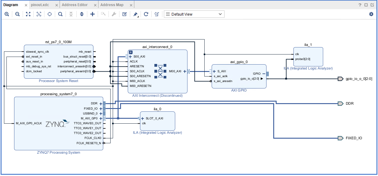
    Can you post a picture of your BLOCK DESIGN and ADDRESS MAPPING from Vivado?

    • Cancel
    • Vote Up 0 Vote Down
    • Sign in to reply
    • Verify Answer
    • Cancel
  • Maxzed
    0 Maxzed 7 months ago in reply to iksevas

    imageimage

    I also tried to "Make External" the GPIO from AXI GPIO (without ILA).
    Same results.....

    • Cancel
    • Vote Up 0 Vote Down
    • Sign in to reply
    • Verify Answer
    • Cancel
  • Maxzed
    0 Maxzed 7 months ago in reply to Maxzed

    This is my xdc

    # Pin JX2 13
    set_property PACKAGE_PIN G14 [get_ports gpio_io_o_0[0]]
    set_property IOSTANDARD LVCMOS33 [get_ports gpio_io_o_0[0]]

    # Pin JX2 14
    set_property PACKAGE_PIN J15 [get_ports gpio_io_o_0[1]]
    set_property IOSTANDARD LVCMOS33 [get_ports gpio_io_o_0[1]]

    # Pin JX2 24
    set_property PACKAGE_PIN D19 [get_ports gpio_io_o_0[2]]
    set_property IOSTANDARD LVCMOS33 [get_ports gpio_io_o_0[2]]

    • Cancel
    • Vote Up 0 Vote Down
    • Sign in to reply
    • Verify Answer
    • Cancel
  • iksevas
    0 iksevas 7 months ago in reply to Maxzed

    One more thing - the top level HDL file - can you post a snippet of the port map?

    • Cancel
    • Vote Up 0 Vote Down
    • Sign in to reply
    • Verify Answer
    • Cancel
  • Maxzed
    0 Maxzed 7 months ago in reply to iksevas

    You mean this?

    --Copyright 1986-2022 Xilinx, Inc. All Rights Reserved.
    --Copyright 2022-2024 Advanced Micro Devices, Inc. All Rights Reserved.
    ----------------------------------------------------------------------------------
    --Tool Version: Vivado v.2024.2 (win64) Build 5239630 Fri Nov 08 22:35:27 MST 2024
    --Date        : Thu Feb 13 15:17:19 2025
    --Host        : C1845 running 64-bit major release  (build 9200)
    --Command     : generate_target design_1_wrapper.bd
    --Design      : design_1_wrapper
    --Purpose     : IP block netlist
    ----------------------------------------------------------------------------------
    library IEEE;
    use IEEE.STD_LOGIC_1164.ALL;
    library UNISIM;
    use UNISIM.VCOMPONENTS.ALL;
    entity design_1_wrapper is
      port (
        DDR_addr : inout STD_LOGIC_VECTOR ( 14 downto 0 );
        DDR_ba : inout STD_LOGIC_VECTOR ( 2 downto 0 );
        DDR_cas_n : inout STD_LOGIC;
        DDR_ck_n : inout STD_LOGIC;
        DDR_ck_p : inout STD_LOGIC;
        DDR_cke : inout STD_LOGIC;
        DDR_cs_n : inout STD_LOGIC;
        DDR_dm : inout STD_LOGIC_VECTOR ( 3 downto 0 );
        DDR_dq : inout STD_LOGIC_VECTOR ( 31 downto 0 );
        DDR_dqs_n : inout STD_LOGIC_VECTOR ( 3 downto 0 );
        DDR_dqs_p : inout STD_LOGIC_VECTOR ( 3 downto 0 );
        DDR_odt : inout STD_LOGIC;
        DDR_ras_n : inout STD_LOGIC;
        DDR_reset_n : inout STD_LOGIC;
        DDR_we_n : inout STD_LOGIC;
        FIXED_IO_ddr_vrn : inout STD_LOGIC;
        FIXED_IO_ddr_vrp : inout STD_LOGIC;
        FIXED_IO_mio : inout STD_LOGIC_VECTOR ( 53 downto 0 );
        FIXED_IO_ps_clk : inout STD_LOGIC;
        FIXED_IO_ps_porb : inout STD_LOGIC;
        FIXED_IO_ps_srstb : inout STD_LOGIC;
        gpio_io_o_0 : out STD_LOGIC_VECTOR ( 2 downto 0 )
      );
    end design_1_wrapper;
    
    architecture STRUCTURE of design_1_wrapper is
      component design_1 is
      port (
        DDR_cas_n : inout STD_LOGIC;
        DDR_cke : inout STD_LOGIC;
        DDR_ck_n : inout STD_LOGIC;
        DDR_ck_p : inout STD_LOGIC;
        DDR_cs_n : inout STD_LOGIC;
        DDR_reset_n : inout STD_LOGIC;
        DDR_odt : inout STD_LOGIC;
        DDR_ras_n : inout STD_LOGIC;
        DDR_we_n : inout STD_LOGIC;
        DDR_ba : inout STD_LOGIC_VECTOR ( 2 downto 0 );
        DDR_addr : inout STD_LOGIC_VECTOR ( 14 downto 0 );
        DDR_dm : inout STD_LOGIC_VECTOR ( 3 downto 0 );
        DDR_dq : inout STD_LOGIC_VECTOR ( 31 downto 0 );
        DDR_dqs_n : inout STD_LOGIC_VECTOR ( 3 downto 0 );
        DDR_dqs_p : inout STD_LOGIC_VECTOR ( 3 downto 0 );
        FIXED_IO_mio : inout STD_LOGIC_VECTOR ( 53 downto 0 );
        FIXED_IO_ddr_vrn : inout STD_LOGIC;
        FIXED_IO_ddr_vrp : inout STD_LOGIC;
        FIXED_IO_ps_srstb : inout STD_LOGIC;
        FIXED_IO_ps_clk : inout STD_LOGIC;
        FIXED_IO_ps_porb : inout STD_LOGIC;
        gpio_io_o_0 : out STD_LOGIC_VECTOR ( 2 downto 0 )
      );
      end component design_1;
      
      attribute MARK_DEBUG : string;
      attribute MARK_DEBUG of gpio_io_o_0: signal is "TRUE";
      
      
    begin
    design_1_i: component design_1
         port map (
          DDR_addr(14 downto 0) => DDR_addr(14 downto 0),
          DDR_ba(2 downto 0) => DDR_ba(2 downto 0),
          DDR_cas_n => DDR_cas_n,
          DDR_ck_n => DDR_ck_n,
          DDR_ck_p => DDR_ck_p,
          DDR_cke => DDR_cke,
          DDR_cs_n => DDR_cs_n,
          DDR_dm(3 downto 0) => DDR_dm(3 downto 0),
          DDR_dq(31 downto 0) => DDR_dq(31 downto 0),
          DDR_dqs_n(3 downto 0) => DDR_dqs_n(3 downto 0),
          DDR_dqs_p(3 downto 0) => DDR_dqs_p(3 downto 0),
          DDR_odt => DDR_odt,
          DDR_ras_n => DDR_ras_n,
          DDR_reset_n => DDR_reset_n,
          DDR_we_n => DDR_we_n,
          FIXED_IO_ddr_vrn => FIXED_IO_ddr_vrn,
          FIXED_IO_ddr_vrp => FIXED_IO_ddr_vrp,
          FIXED_IO_mio(53 downto 0) => FIXED_IO_mio(53 downto 0),
          FIXED_IO_ps_clk => FIXED_IO_ps_clk,
          FIXED_IO_ps_porb => FIXED_IO_ps_porb,
          FIXED_IO_ps_srstb => FIXED_IO_ps_srstb,
          gpio_io_o_0(2 downto 0) => gpio_io_o_0(2 downto 0)
        );
    end STRUCTURE;
    

    • Cancel
    • Vote Up 0 Vote Down
    • Sign in to reply
    • Verify Answer
    • Cancel
  • iksevas
    0 iksevas 7 months ago in reply to Maxzed

    Everything looks in order from Vivado standpoint. What about your Petalinux setup?  

    https://xilinx-wiki.atlassian.net/wiki/spaces/A/pages/18841846/AXI+GPIO

    Look at this link for requirements in the kernel and population of the device tree. They also give you the command line calls. It "should just work".

    • Cancel
    • Vote Up 0 Vote Down
    • Sign in to reply
    • Verify Answer
    • Cancel
>
element14 Community

element14 is the first online community specifically for engineers. Connect with your peers and get expert answers to your questions.

  • Members
  • Learn
  • Technologies
  • Challenges & Projects
  • Products
  • Store
  • About Us
  • Feedback & Support
  • FAQs
  • Terms of Use
  • Privacy Policy
  • Legal and Copyright Notices
  • Sitemap
  • Cookies

An Avnet Company © 2025 Premier Farnell Limited. All Rights Reserved.

Premier Farnell Ltd, registered in England and Wales (no 00876412), registered office: Farnell House, Forge Lane, Leeds LS12 2NE.

ICP 备案号 10220084.

Follow element14

  • X
  • Facebook
  • linkedin
  • YouTube