element14 Community
element14 Community
    Register Log In
  • Site
  • Search
  • Log In Register
  • About Us
  • Community Hub
    Community Hub
    • What's New on element14
    • Feedback and Support
    • Benefits of Membership
    • Personal Blogs
    • Members Area
    • Achievement Levels
  • Learn
    Learn
    • Ask an Expert
    • eBooks
    • element14 presents
    • Learning Center
    • Tech Spotlight
    • STEM Academy
    • Webinars, Training and Events
    • Learning Groups
  • Technologies
    Technologies
    • 3D Printing
    • FPGA
    • Industrial Automation
    • Internet of Things
    • Power & Energy
    • Sensors
    • Technology Groups
  • Challenges & Projects
    Challenges & Projects
    • Design Challenges
    • element14 presents Projects
    • Project14
    • Arduino Projects
    • Raspberry Pi Projects
    • Project Groups
  • Products
    Products
    • Arduino
    • Avnet Boards Community
    • Dev Tools
    • Manufacturers
    • Multicomp Pro
    • Product Groups
    • Raspberry Pi
    • RoadTests & Reviews
  • Store
    Store
    • Visit Your Store
    • Choose another store...
      • Europe
      •  Austria (German)
      •  Belgium (Dutch, French)
      •  Bulgaria (Bulgarian)
      •  Czech Republic (Czech)
      •  Denmark (Danish)
      •  Estonia (Estonian)
      •  Finland (Finnish)
      •  France (French)
      •  Germany (German)
      •  Hungary (Hungarian)
      •  Ireland
      •  Israel
      •  Italy (Italian)
      •  Latvia (Latvian)
      •  
      •  Lithuania (Lithuanian)
      •  Netherlands (Dutch)
      •  Norway (Norwegian)
      •  Poland (Polish)
      •  Portugal (Portuguese)
      •  Romania (Romanian)
      •  Russia (Russian)
      •  Slovakia (Slovak)
      •  Slovenia (Slovenian)
      •  Spain (Spanish)
      •  Sweden (Swedish)
      •  Switzerland(German, French)
      •  Turkey (Turkish)
      •  United Kingdom
      • Asia Pacific
      •  Australia
      •  China
      •  Hong Kong
      •  India
      •  Korea (Korean)
      •  Malaysia
      •  New Zealand
      •  Philippines
      •  Singapore
      •  Taiwan
      •  Thailand (Thai)
      • Americas
      •  Brazil (Portuguese)
      •  Canada
      •  Mexico (Spanish)
      •  United States
      Can't find the country/region you're looking for? Visit our export site or find a local distributor.
  • Translate
  • Profile
  • Settings
Avnet Boards Forums
  • Products
  • Dev Tools
  • Avnet Boards Community
  • Avnet Boards Forums
  • More
  • Cancel
Avnet Boards Forums
MicroZed Hardware Design AXI GPIO PL
  • Forum
  • Documents
  • Members
  • Mentions
  • Sub-Groups
  • Tags
  • More
  • Cancel
  • New
Join Avnet Boards Forums to participate - click to join for free!
Actions
  • Share
  • More
  • Cancel
Forum Thread Details
  • State Suggested Answer
  • Replies 13 replies
  • Answers 1 answer
  • Subscribers 324 subscribers
  • Views 1066 views
  • Users 0 members are here
Related

AXI GPIO PL

Maxzed
Maxzed 7 months ago

Dear all,

This is my first post, so please be patient if I make any mistakes.

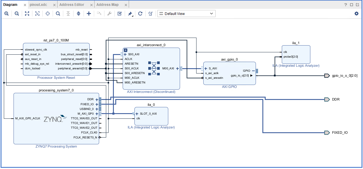
I am working with a MicroZed board, using Vivado 2024 and PetaLinux 2024. I am following some tutorials to create a simple project with:

  • Zynq processor
  • AXI GPIO

Goal:

I want to control a GPIO on JX2 of the MicroZed.

  • The specific pin is pin 13 on JX2, which corresponds to G14 on bank 35.

My XDC file:

set_property PACKAGE_PIN G14 [get_ports gpio_io_o_0[0]]
set_property IOSTANDARD LVCMOS33 [get_ports gpio_io_o_0[0]]

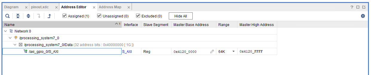
I created my Vivado project, assigned an address to the AXI GPIO interface, and built my PetaLinux project. I then booted the MicroZed using an SD card.

Everything seems to work correctly. Running the following command:

ls -lh /sys/class/gpio

I get:

--w------- 1 root root 4.0K Jan 1 1970 export
lrwxrwxrwx 1 root root 0 Jan 1 1970 gpiochip512 -> ../../devices/soc0/pl-bus/41200000.gpio/gpio/gpiochip512
lrwxrwxrwx 1 root root 0 Jan 1 1970 gpiochip515 -> ../../devices/soc0/axi/e000a000.gpio/gpio/gpiochip515
--w------- 1 root root 4.0K Jan 1 1970 unexport

This confirms that gpiochip512 is correctly mapped to my PL AXI GPIO.

I also added an ILA (Integrated Logic Analyzer) in my PL design. When I toggle the GPIO with:


echo 1 > /sys/class/gpio/gpio512/value

I can see the GPIO signal changing in the ILA.

Issue:

However, when I check the physical pin (JX2, pin 13) with an oscilloscope, I see no signal change.

Has anyone encountered a similar issue? Any suggestions on what I might be missing?

Thanks in advance for your help!

  • Sign in to reply
  • Cancel

Top Replies

  • Maxzed
    Maxzed 7 months ago in reply to Maxzed +1 suggested
    Here we go. My fault: I was thinking like a software engineer rather than an electronics engineer: the GPIO banks on the MicroZed are not powered but expect an external power supply. I do not have right…
Parents
  • iksevas
    0 iksevas 7 months ago

    Did you set the GPIO direction to be OUTPUT?

    • Cancel
    • Vote Up 0 Vote Down
    • Sign in to reply
    • Verify Answer
    • Cancel
  • Maxzed
    0 Maxzed 7 months ago in reply to iksevas

    Hi, thanks for you answer.
    Yes it is set as output
    First step -> export
    Second step -> set out as direction
    Third step -> change value

    Also in the AXI GPIO, it is set as output: as soon as I make the wrapper, it is recognized to be out.

    • Cancel
    • Vote Up 0 Vote Down
    • Sign in to reply
    • Verify Answer
    • Cancel
  • iksevas
    0 iksevas 7 months ago in reply to Maxzed

    My understanding is something changed with sysfs in the latest version of the tools. Not sure what yet. I’ll ask for clarification.

    • Cancel
    • Vote Up 0 Vote Down
    • Sign in to reply
    • Verify Answer
    • Cancel
  • Maxzed
    0 Maxzed 7 months ago in reply to iksevas

    I can see the signal moving in the ILA I placed in the PL.
    My feeling is that the /sys/class/gpio part is working... 

    • Cancel
    • Vote Up 0 Vote Down
    • Sign in to reply
    • Verify Answer
    • Cancel
  • iksevas
    0 iksevas 7 months ago in reply to Maxzed

    Can you post a picture of your BLOCK DESIGN and ADDRESS MAPPING from Vivado?

    • Cancel
    • Vote Up 0 Vote Down
    • Sign in to reply
    • Verify Answer
    • Cancel
  • Maxzed
    0 Maxzed 7 months ago in reply to iksevas

    imageimage

    I also tried to "Make External" the GPIO from AXI GPIO (without ILA).
    Same results.....

    • Cancel
    • Vote Up 0 Vote Down
    • Sign in to reply
    • Verify Answer
    • Cancel
  • Maxzed
    0 Maxzed 7 months ago in reply to Maxzed

    This is my xdc

    # Pin JX2 13
    set_property PACKAGE_PIN G14 [get_ports gpio_io_o_0[0]]
    set_property IOSTANDARD LVCMOS33 [get_ports gpio_io_o_0[0]]

    # Pin JX2 14
    set_property PACKAGE_PIN J15 [get_ports gpio_io_o_0[1]]
    set_property IOSTANDARD LVCMOS33 [get_ports gpio_io_o_0[1]]

    # Pin JX2 24
    set_property PACKAGE_PIN D19 [get_ports gpio_io_o_0[2]]
    set_property IOSTANDARD LVCMOS33 [get_ports gpio_io_o_0[2]]

    • Cancel
    • Vote Up 0 Vote Down
    • Sign in to reply
    • Verify Answer
    • Cancel
  • iksevas
    0 iksevas 7 months ago in reply to Maxzed

    One more thing - the top level HDL file - can you post a snippet of the port map?

    • Cancel
    • Vote Up 0 Vote Down
    • Sign in to reply
    • Verify Answer
    • Cancel
  • Maxzed
    0 Maxzed 7 months ago in reply to iksevas

    You mean this?

    --Copyright 1986-2022 Xilinx, Inc. All Rights Reserved.
    --Copyright 2022-2024 Advanced Micro Devices, Inc. All Rights Reserved.
    ----------------------------------------------------------------------------------
    --Tool Version: Vivado v.2024.2 (win64) Build 5239630 Fri Nov 08 22:35:27 MST 2024
    --Date        : Thu Feb 13 15:17:19 2025
    --Host        : C1845 running 64-bit major release  (build 9200)
    --Command     : generate_target design_1_wrapper.bd
    --Design      : design_1_wrapper
    --Purpose     : IP block netlist
    ----------------------------------------------------------------------------------
    library IEEE;
    use IEEE.STD_LOGIC_1164.ALL;
    library UNISIM;
    use UNISIM.VCOMPONENTS.ALL;
    entity design_1_wrapper is
      port (
        DDR_addr : inout STD_LOGIC_VECTOR ( 14 downto 0 );
        DDR_ba : inout STD_LOGIC_VECTOR ( 2 downto 0 );
        DDR_cas_n : inout STD_LOGIC;
        DDR_ck_n : inout STD_LOGIC;
        DDR_ck_p : inout STD_LOGIC;
        DDR_cke : inout STD_LOGIC;
        DDR_cs_n : inout STD_LOGIC;
        DDR_dm : inout STD_LOGIC_VECTOR ( 3 downto 0 );
        DDR_dq : inout STD_LOGIC_VECTOR ( 31 downto 0 );
        DDR_dqs_n : inout STD_LOGIC_VECTOR ( 3 downto 0 );
        DDR_dqs_p : inout STD_LOGIC_VECTOR ( 3 downto 0 );
        DDR_odt : inout STD_LOGIC;
        DDR_ras_n : inout STD_LOGIC;
        DDR_reset_n : inout STD_LOGIC;
        DDR_we_n : inout STD_LOGIC;
        FIXED_IO_ddr_vrn : inout STD_LOGIC;
        FIXED_IO_ddr_vrp : inout STD_LOGIC;
        FIXED_IO_mio : inout STD_LOGIC_VECTOR ( 53 downto 0 );
        FIXED_IO_ps_clk : inout STD_LOGIC;
        FIXED_IO_ps_porb : inout STD_LOGIC;
        FIXED_IO_ps_srstb : inout STD_LOGIC;
        gpio_io_o_0 : out STD_LOGIC_VECTOR ( 2 downto 0 )
      );
    end design_1_wrapper;
    
    architecture STRUCTURE of design_1_wrapper is
      component design_1 is
      port (
        DDR_cas_n : inout STD_LOGIC;
        DDR_cke : inout STD_LOGIC;
        DDR_ck_n : inout STD_LOGIC;
        DDR_ck_p : inout STD_LOGIC;
        DDR_cs_n : inout STD_LOGIC;
        DDR_reset_n : inout STD_LOGIC;
        DDR_odt : inout STD_LOGIC;
        DDR_ras_n : inout STD_LOGIC;
        DDR_we_n : inout STD_LOGIC;
        DDR_ba : inout STD_LOGIC_VECTOR ( 2 downto 0 );
        DDR_addr : inout STD_LOGIC_VECTOR ( 14 downto 0 );
        DDR_dm : inout STD_LOGIC_VECTOR ( 3 downto 0 );
        DDR_dq : inout STD_LOGIC_VECTOR ( 31 downto 0 );
        DDR_dqs_n : inout STD_LOGIC_VECTOR ( 3 downto 0 );
        DDR_dqs_p : inout STD_LOGIC_VECTOR ( 3 downto 0 );
        FIXED_IO_mio : inout STD_LOGIC_VECTOR ( 53 downto 0 );
        FIXED_IO_ddr_vrn : inout STD_LOGIC;
        FIXED_IO_ddr_vrp : inout STD_LOGIC;
        FIXED_IO_ps_srstb : inout STD_LOGIC;
        FIXED_IO_ps_clk : inout STD_LOGIC;
        FIXED_IO_ps_porb : inout STD_LOGIC;
        gpio_io_o_0 : out STD_LOGIC_VECTOR ( 2 downto 0 )
      );
      end component design_1;
      
      attribute MARK_DEBUG : string;
      attribute MARK_DEBUG of gpio_io_o_0: signal is "TRUE";
      
      
    begin
    design_1_i: component design_1
         port map (
          DDR_addr(14 downto 0) => DDR_addr(14 downto 0),
          DDR_ba(2 downto 0) => DDR_ba(2 downto 0),
          DDR_cas_n => DDR_cas_n,
          DDR_ck_n => DDR_ck_n,
          DDR_ck_p => DDR_ck_p,
          DDR_cke => DDR_cke,
          DDR_cs_n => DDR_cs_n,
          DDR_dm(3 downto 0) => DDR_dm(3 downto 0),
          DDR_dq(31 downto 0) => DDR_dq(31 downto 0),
          DDR_dqs_n(3 downto 0) => DDR_dqs_n(3 downto 0),
          DDR_dqs_p(3 downto 0) => DDR_dqs_p(3 downto 0),
          DDR_odt => DDR_odt,
          DDR_ras_n => DDR_ras_n,
          DDR_reset_n => DDR_reset_n,
          DDR_we_n => DDR_we_n,
          FIXED_IO_ddr_vrn => FIXED_IO_ddr_vrn,
          FIXED_IO_ddr_vrp => FIXED_IO_ddr_vrp,
          FIXED_IO_mio(53 downto 0) => FIXED_IO_mio(53 downto 0),
          FIXED_IO_ps_clk => FIXED_IO_ps_clk,
          FIXED_IO_ps_porb => FIXED_IO_ps_porb,
          FIXED_IO_ps_srstb => FIXED_IO_ps_srstb,
          gpio_io_o_0(2 downto 0) => gpio_io_o_0(2 downto 0)
        );
    end STRUCTURE;
    

    • Cancel
    • Vote Up 0 Vote Down
    • Sign in to reply
    • Verify Answer
    • Cancel
  • iksevas
    0 iksevas 7 months ago in reply to Maxzed

    Everything looks in order from Vivado standpoint. What about your Petalinux setup?  

    https://xilinx-wiki.atlassian.net/wiki/spaces/A/pages/18841846/AXI+GPIO

    Look at this link for requirements in the kernel and population of the device tree. They also give you the command line calls. It "should just work".

    • Cancel
    • Vote Up 0 Vote Down
    • Sign in to reply
    • Verify Answer
    • Cancel
  • Maxzed
    0 Maxzed 7 months ago in reply to iksevas

    I think the Petalinux setup to be ok.
    I can see the GPIO moving in the ILA. It means that the AXI GPIO registers are written correctly and the IP is doing what it has to do.
    If there were an issue at the Petalinux level, I shouldn't see the signal moving in the ILA...I guess...

    • Cancel
    • Vote Up 0 Vote Down
    • Sign in to reply
    • Verify Answer
    • Cancel
Reply
  • Maxzed
    0 Maxzed 7 months ago in reply to iksevas

    I think the Petalinux setup to be ok.
    I can see the GPIO moving in the ILA. It means that the AXI GPIO registers are written correctly and the IP is doing what it has to do.
    If there were an issue at the Petalinux level, I shouldn't see the signal moving in the ILA...I guess...

    • Cancel
    • Vote Up 0 Vote Down
    • Sign in to reply
    • Verify Answer
    • Cancel
Children
  • Maxzed
    0 Maxzed 7 months ago in reply to Maxzed

    Here we go.
    My fault: 
    I was thinking like a software engineer rather than an electronics engineer:
    the GPIO banks on the MicroZed are not powered but expect an external power supply.

    I do not have right now an external power supply.

    But I will have it.

    Thanks a lot for your help.

    Regards.

    • Cancel
    • Vote Up +1 Vote Down
    • Sign in to reply
    • Verify Answer
    • Reject Answer
    • Cancel
  • iksevas
    0 iksevas 7 months ago in reply to Maxzed

    Makes sense if you are using MicroZed standalone and not with Carrier Card. The Carrier Card provides power to the PL banks like you mentioned. Standalone you are limited to MIO.

    • Cancel
    • Vote Up 0 Vote Down
    • Sign in to reply
    • Verify Answer
    • Cancel
element14 Community

element14 is the first online community specifically for engineers. Connect with your peers and get expert answers to your questions.

  • Members
  • Learn
  • Technologies
  • Challenges & Projects
  • Products
  • Store
  • About Us
  • Feedback & Support
  • FAQs
  • Terms of Use
  • Privacy Policy
  • Legal and Copyright Notices
  • Sitemap
  • Cookies

An Avnet Company © 2025 Premier Farnell Limited. All Rights Reserved.

Premier Farnell Ltd, registered in England and Wales (no 00876412), registered office: Farnell House, Forge Lane, Leeds LS12 2NE.

ICP 备案号 10220084.

Follow element14

  • X
  • Facebook
  • linkedin
  • YouTube