element14 Community
element14 Community
    Register Log In
  • Site
  • Search
  • Log In Register
  • Community Hub
    Community Hub
    • What's New on element14
    • Feedback and Support
    • Benefits of Membership
    • Personal Blogs
    • Members Area
    • Achievement Levels
  • Learn
    Learn
    • Ask an Expert
    • eBooks
    • element14 presents
    • Learning Center
    • Tech Spotlight
    • STEM Academy
    • Webinars, Training and Events
    • Learning Groups
  • Technologies
    Technologies
    • 3D Printing
    • FPGA
    • Industrial Automation
    • Internet of Things
    • Power & Energy
    • Sensors
    • Technology Groups
  • Challenges & Projects
    Challenges & Projects
    • Design Challenges
    • element14 presents Projects
    • Project14
    • Arduino Projects
    • Raspberry Pi Projects
    • Project Groups
  • Products
    Products
    • Arduino
    • Avnet & Tria Boards Community
    • Dev Tools
    • Manufacturers
    • Multicomp Pro
    • Product Groups
    • Raspberry Pi
    • RoadTests & Reviews
  • About Us
    About the element14 Community
  • Store
    Store
    • Visit Your Store
    • Choose another store...
      • Europe
      •  Austria (German)
      •  Belgium (Dutch, French)
      •  Bulgaria (Bulgarian)
      •  Czech Republic (Czech)
      •  Denmark (Danish)
      •  Estonia (Estonian)
      •  Finland (Finnish)
      •  France (French)
      •  Germany (German)
      •  Hungary (Hungarian)
      •  Ireland
      •  Israel
      •  Italy (Italian)
      •  Latvia (Latvian)
      •  
      •  Lithuania (Lithuanian)
      •  Netherlands (Dutch)
      •  Norway (Norwegian)
      •  Poland (Polish)
      •  Portugal (Portuguese)
      •  Romania (Romanian)
      •  Russia (Russian)
      •  Slovakia (Slovak)
      •  Slovenia (Slovenian)
      •  Spain (Spanish)
      •  Sweden (Swedish)
      •  Switzerland(German, French)
      •  Turkey (Turkish)
      •  United Kingdom
      • Asia Pacific
      •  Australia
      •  China
      •  Hong Kong
      •  India
      •  Japan
      •  Korea (Korean)
      •  Malaysia
      •  New Zealand
      •  Philippines
      •  Singapore
      •  Taiwan
      •  Thailand (Thai)
      •  Vietnam
      • Americas
      •  Brazil (Portuguese)
      •  Canada
      •  Mexico (Spanish)
      •  United States
      Can't find the country/region you're looking for? Visit our export site or find a local distributor.
  • Translate
  • Profile
  • Settings
Avnet Boards Forums
  • Products
  • Dev Tools
  • Avnet & Tria Boards Community
  • Avnet Boards Forums
  • More
  • Cancel
Avnet Boards Forums
ZedBoard Hardware Design Implementing and verifying CAN Controller on ZedBoard
  • Forum
  • Documents
  • Members
  • Mentions
  • Sub-Groups
  • Tags
  • More
  • Cancel
  • New
Join Avnet Boards Forums to participate - click to join for free!
Actions
  • Share
  • More
  • Cancel
Forum Thread Details
  • State Not Answered
  • Replies 3 replies
  • Subscribers 353 subscribers
  • Views 1534 views
  • Users 0 members are here
Related

Implementing and verifying CAN Controller on ZedBoard

Former Member
Former Member over 12 years ago

Hi everybody,

I'm currently trying to implement the CAN Controller from the PS into a design of mine.
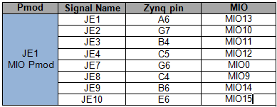
The frist step was just to activate the CAN0 in the XPS and then making the synthesis work in Plan Ahead. I read in the Hardware User Guide, that the Pmod JE has hardwired connections to specific MIO-pins. Is that correct?
For instance, if I select MIO_14 and 15 for CAN_Rx and CAN_Tx, the signals would already be at the respective Pmod connection.

I tested the CAN Controller with the example codes and it all works fine when the Controller is in loopback mode. However, once I change the mode to normal and want to manually loopback Tx to Rx, it doesn't work anymore.

Can somebody give me a quick tutorial on how to implement the CAN Controller, just to rule out any design problems? Initially I thought that if the loopback modes work, the implementation is fine but now I'm not so sure anymore. Or does the CAN Controller need any specific hardware on the Zedboard? I have an external transceiver but since I don't even get the Tx signal out of the board, I'm pretty sure that that is not the problem.

Regards

  • Sign in to reply
  • Cancel
  • bhfletcher
    0 bhfletcher over 12 years ago

    Check out this AR -- http://www.xilinx.com/support/answers/55133.htm

    JE does have hard-wired connections to the MIO. Here's a table from the ZedBoard UG with an MIO column added. If you configured the CAN controller to connect to MIOs 14, 15, then you should be looking at JE9 and JE10.

    image

    It might be helpful if you share your code for setting up the CAN controller.

    Bryan

    • Cancel
    • Vote Up 0 Vote Down
    • Sign in to reply
    • Verify Answer
    • Cancel
  • Former Member
    0 Former Member over 12 years ago in reply to bhfletcher

    Thank you Bryan for your response.

    I actually just used the xcanps_polled_example.c example from Xilinx ISE. Instead of loopback mode I just inserted nomrmal mode and thought that it should work, when I connect the Rx and Tx port of the Pmod.

    * @file xcanps_polled_example.c
    *
    * Contains an example of how to use the XCanPs driver directly.
    * This example shows the using the driver/device in polled mode.


    #include "xcanps.h"
    #include "xparameters.h"
    #include "xil_printf.h"


    #define CAN_DEVICE_IDtXPAR_XCANPS_0_DEVICE_ID


    #define XCANPS_MAX_FRAME_SIZE_IN_WORDS (XCANPS_MAX_FRAME_SIZE / sizeof(u32))

    #define FRAME_DATA_LENGTH tt8  /* Frame Data field length */


    #define TEST_MESSAGE_IDttt2000

    /*
    * The Baud Rate Prescaler Register (BRPR) and Bit Timing Register (BTR)
    * are setup such that CAN baud rate equals 40Kbps, assuming that the
    * the CAN clock is 24MHz. The user needs to modify these values based on
    * the desired baud rate and the CAN clock frequency. For more information
    * see the CAN 2.0A, CAN 2.0B, ISO 11898-1 specifications.
    */

    /*
    * Timing parameters to be set in the Bit Timing Register (BTR).
    * These values are for a 40 Kbps baudrate assuming the CAN input clock
    frequency
    * is 24 MHz.
    */
    #define TEST_BTR_SYNCJUMPWIDTHtt1
    #define TEST_BTR_SECOND_TIMESEGMENTt3
    #define TEST_BTR_FIRST_TIMESEGMENTt8

    /*
    * The Baud rate Prescalar value in the Baud Rate Prescaler Register (BRPR)
    * needs to be set based on the input clock  frequency to the CAN core and
    * the desired CAN baud rate.
    * This value is for a 40 Kbps baudrate assuming the CAN input clock frequency
    * is 24 MHz.
    */
    #define TEST_BRPR_BAUD_PRESCALARt1


    int CanPsPolledExample(u16 DeviceId);
    static int SendFrame(XCanPs *InstancePtr);
    static int RecvFrame(XCanPs *InstancePtr);


    /*
    * Buffers to hold frames to send and receive. These are declared as global so
    * that they are not on the stack.
    * These buffers need to be 32-bit aligned
    */
    static u32 TxFrame[XCANPS_MAX_FRAME_SIZE_IN_WORDS];
    static u32 RxFrame[XCANPS_MAX_FRAME_SIZE_IN_WORDS];

    /* Driver instance */
    static XCanPs Can;


    * This function is the main function of the Can polled example.
    *
    * @paramtNone
    *
    * @return
    *tt- XST_SUCCESS if the example has completed successfully.
    *tt- XST_FAILURE if the example has failed.
    *
    * @notettNone
    *
    *****************************************************************************/
    #ifndef TESTAPP_GEN
    int main()
    {
    tint Status;

    txil_printf("CAN Polled Mode Example Test r
    ");

    t/*
    t * Run the Can Polled example, specify the Device ID that is generated
    t * in xparameters.h .
    t */
    tStatus = CanPsPolledExample(CAN_DEVICE_ID);
    tif (Status != XST_SUCCESS) {
    ttxil_printf("CAN Polled Mode Example Test Failedr
    ");
    ttreturn XST_FAILURE;
    t}

    txil_printf("Successfully ran CAN Polled Mode Example Testr
    ");
    treturn XST_SUCCESS;
    }
    #endif

    /*****************************************************************************/
    /**
    *
    * The entry point for showing the XCanPs driver in polled mode. The example
    * configures the device for normal mode, then sends a Can
    * frame, receives the same Can frame, and verifies the frame contents.
    *
    * @paramtDeviceId is the XPAR_<CANPS_instance>_DEVICE_ID value from
    *ttxparameters.h
    *
    * @returntXST_SUCCESS if successful, otherwise driver-specific error code.
    *
    * @note
    *
    * If the device is not working correctly, this function may enter an infinite
    * loop and will never return to the caller.
    *
    ******************************************************************************/
    int CanPsPolledExample(u16 DeviceId)
    {
    tint Status;
    tXCanPs *CanInstPtr = &Can;
    tXCanPs_Config *ConfigPtr;

    t/*
    t * Initialize the Can device.
    t */
    tConfigPtr = XCanPs_LookupConfig(DeviceId);
    tif (CanInstPtr == NULL) {
    ttreturn XST_FAILURE;
    t}
    tStatus = XCanPs_CfgInitialize(CanInstPtr,
    tttttConfigPtr,
    tttttConfigPtr->BaseAddr);
    tif (Status != XST_SUCCESS) {
    ttreturn XST_FAILURE;
    t}

    t/*
    t * Run self-test on the device, which verifies basic sanity of the
    t * device and the driver.
    t */
    tStatus = XCanPs_SelfTest(CanInstPtr);
    tif (Status != XST_SUCCESS) {
    ttreturn XST_FAILURE;
    t}

    t/*
    t * Enter Configuration Mode so we can setup Baud Rate Prescaler
    t * Register (BRPR) and Bit Timing Register (BTR).
    t */
    tXCanPs_EnterMode(CanInstPtr, XCANPS_MODE_CONFIG);
    twhile(XCanPs_GetMode(CanInstPtr) != XCANPS_MODE_CONFIG);

    t/*
    t * Setup Baud Rate Prescaler Register (BRPR) and
    t * Bit Timing Register (BTR).
    t */
    tXCanPs_SetBaudRatePrescaler(CanInstPtr, TEST_BRPR_BAUD_PRESCALAR);
    tXCanPs_SetBitTiming(CanInstPtr, TEST_BTR_SYNCJUMPWIDTH,
    ttttTEST_BTR_SECOND_TIMESEGMENT,

    ttttTEST_BTR_FIRST_TIMESEGMENT);

    t/*
    t * Enter Normal Mode.
    t */
    tXCanPs_EnterMode(CanInstPtr, XCANPS_MODE_NORMAL);
    twhile(XCanPs_GetMode(CanInstPtr) != XCANPS_MODE_NORMAL);

    t/*
    t * Send a frame, receive the frame via the loop back and verify its
    t * contents.
    t */
    tStatus = SendFrame(CanInstPtr);
    tif (Status != XST_SUCCESS) {
    ttreturn Status;
    t}

    tStatus = RecvFrame(CanInstPtr);

    treturn Status;
    }


    static int SendFrame(XCanPs *InstancePtr)
    {
    tu8 *FramePtr;
    tint Index;
    tint Status;

    t/*
    t * Create correct values for Identifier and Data Length Code Register.
    t */
    tTxFrame[0] = (u32)XCanPs_CreateIdValue((u32)TEST_MESSAGE_ID, 0, 0, 0, 0);
    tTxFrame[1] = (u32)XCanPs_CreateDlcValue((u32)FRAME_DATA_LENGTH);

    t/*
    t * Now fill in the data field with known values so we can verify them
    t * on receive.
    t */
    tFramePtr = (u8 *)(&TxFrame[2]);
    tfor (Index = 0; Index < FRAME_DATA_LENGTH; Index++) {
    tt*FramePtr++ = (u8)Index;
    t}

    t/*
    t * Wait until TX FIFO has room.
    t */
    twhile (XCanPs_IsTxFifoFull(InstancePtr) == TRUE);

    t/*
    t * Now send the frame.
    t *
    t * Another way to send a frame is keep calling XCanPs_Send() until it
    t * returns XST_SUCCESS. No check on if TX FIFO is full is needed anymore
    t * in that case.
    t */
    tStatus = XCanPs_Send(InstancePtr, TxFrame);

    treturn Status;
    }


    /*****************************************************************************/
    /**
    *
    * This function receives a frame and verifies its contents.
    *
    * @paramtInstancePtr is a pointer to the driver instance.
    *
    * @returntXST_SUCCESS if successful, a driver-specific return code if not.
    *
    * @note
    *
    * This function waits until RX FIFO becomes not empty before reading a frame
    * from it. So this function may block if the hardware is not built
    * correctly.
    *
    ******************************************************************************/
    static int RecvFrame(XCanPs *InstancePtr)
    {
    tu8 *FramePtr;
    tint Status;
    tint Index;

    t/*
    t * Wait until a frame is received.
    t */
    twhile (XCanPs_IsRxEmpty(InstancePtr) == TRUE);

    t/*
    t * Receive a frame and verify its contents.
    t */
    tStatus = XCanPs_Recv(InstancePtr, RxFrame);
    tif (Status == XST_SUCCESS) {
    tt/*
    tt * Verify Identifier and Data Length Code.
    tt */
    ttif (RxFrame[0] !=
    ttt(u32)XCanPs_CreateIdValue((u32)TEST_MESSAGE_ID, 0, 0, 0, 0))
    tttreturn XST_LOOPBACK_ERROR;

    ttif ((RxFrame[1] & ~XCANPS_DLCR_TIMESTAMP_MASK) != TxFrame[1])
    tttreturn XST_LOOPBACK_ERROR;

    tt/*
    tt * Verify Data field contents.
    tt */
    ttFramePtr = (u8 *)(&RxFrame[2]);
    ttfor (Index = 0; Index < FRAME_DATA_LENGTH; Index++) {
    tttif (*FramePtr++ != (u8)Index) {
    ttttreturn XST_LOOPBACK_ERROR;
    ttt}
    tt}
    t}

    treturn Status;
    }


    Regards

    • Cancel
    • Vote Up 0 Vote Down
    • Sign in to reply
    • Verify Answer
    • Cancel
  • Former Member
    0 Former Member over 12 years ago

    So i've implemented the Can Controller now and am trying to verify its functionality. This is what I get at the Tx port.
    http://img713.imageshack.us/img713/8601/3r6y.jpg

    It seems I have to do something more to read the frames of the Can Controller. Do I have to short them on ground or Rx with a resistor?

    Thanks

    • Cancel
    • Vote Up 0 Vote Down
    • Sign in to reply
    • Verify Answer
    • Cancel
element14 Community

element14 is the first online community specifically for engineers. Connect with your peers and get expert answers to your questions.

  • Members
  • Learn
  • Technologies
  • Challenges & Projects
  • Products
  • Store
  • About Us
  • Feedback & Support
  • FAQs
  • Terms of Use
  • Privacy Policy
  • Legal and Copyright Notices
  • Sitemap
  • Cookies

An Avnet Company © 2026 Premier Farnell Limited. All Rights Reserved.

Premier Farnell Ltd, registered in England and Wales (no 00876412), registered office: Farnell House, Forge Lane, Leeds LS12 2NE.

ICP 备案号 10220084.

Follow element14

  • X
  • Facebook
  • linkedin
  • YouTube