element14 Community
element14 Community
    Register Log In
  • Site
  • Search
  • Log In Register
  • About Us
  • Community Hub
    Community Hub
    • What's New on element14
    • Feedback and Support
    • Benefits of Membership
    • Personal Blogs
    • Members Area
    • Achievement Levels
  • Learn
    Learn
    • Ask an Expert
    • eBooks
    • element14 presents
    • Learning Center
    • Tech Spotlight
    • STEM Academy
    • Webinars, Training and Events
    • Learning Groups
  • Technologies
    Technologies
    • 3D Printing
    • FPGA
    • Industrial Automation
    • Internet of Things
    • Power & Energy
    • Sensors
    • Technology Groups
  • Challenges & Projects
    Challenges & Projects
    • Design Challenges
    • element14 presents Projects
    • Project14
    • Arduino Projects
    • Raspberry Pi Projects
    • Project Groups
  • Products
    Products
    • Arduino
    • Avnet Boards Community
    • Dev Tools
    • Manufacturers
    • Multicomp Pro
    • Product Groups
    • Raspberry Pi
    • RoadTests & Reviews
  • Store
    Store
    • Visit Your Store
    • Choose another store...
      • Europe
      •  Austria (German)
      •  Belgium (Dutch, French)
      •  Bulgaria (Bulgarian)
      •  Czech Republic (Czech)
      •  Denmark (Danish)
      •  Estonia (Estonian)
      •  Finland (Finnish)
      •  France (French)
      •  Germany (German)
      •  Hungary (Hungarian)
      •  Ireland
      •  Israel
      •  Italy (Italian)
      •  Latvia (Latvian)
      •  
      •  Lithuania (Lithuanian)
      •  Netherlands (Dutch)
      •  Norway (Norwegian)
      •  Poland (Polish)
      •  Portugal (Portuguese)
      •  Romania (Romanian)
      •  Russia (Russian)
      •  Slovakia (Slovak)
      •  Slovenia (Slovenian)
      •  Spain (Spanish)
      •  Sweden (Swedish)
      •  Switzerland(German, French)
      •  Turkey (Turkish)
      •  United Kingdom
      • Asia Pacific
      •  Australia
      •  China
      •  Hong Kong
      •  India
      •  Korea (Korean)
      •  Malaysia
      •  New Zealand
      •  Philippines
      •  Singapore
      •  Taiwan
      •  Thailand (Thai)
      • Americas
      •  Brazil (Portuguese)
      •  Canada
      •  Mexico (Spanish)
      •  United States
      Can't find the country/region you're looking for? Visit our export site or find a local distributor.
  • Translate
  • Profile
  • Settings
Avnet Boards Forums
  • Products
  • Dev Tools
  • Avnet Boards Community
  • Avnet Boards Forums
  • More
  • Cancel
Avnet Boards Forums
ZUBoard ZUBoard with AVNET SSD module and PYNQ
  • Forum
  • Documents
  • Members
  • Mentions
  • Sub-Groups
  • Tags
  • More
  • Cancel
  • New
Join Avnet Boards Forums to participate - click to join for free!
Actions
  • Share
  • More
  • Cancel
Forum Thread Details
  • Replies 1 reply
  • Subscribers 327 subscribers
  • Views 37 views
  • Users 0 members are here
  • ssd
  • ZU Board 1CG
  • AVNET ZUB1CG
  • pynq
  • m.2
  • ZUBoard
  • zub1cg
  • zu1cgboard
Related

ZUBoard with AVNET SSD module and PYNQ

tjaekel
tjaekel 1 day ago

After getting AVNET eMMC working fine on ZUBoard PYNQ image (with a modified BSP version, device tree with &sdhci0 added),
I try still to see also SSD/M.2 module working on a ZUBoard PYNQ image...

What works:

  • image the SD card with regular ZUBoard PYNQ image
  • boot via SD card, running on SD Card
  • take the files:
    BOOT.BIN
    image.ub
    from a Petalinux test image, e.g from here:
    https://www.hackster.io/tom-curran/zuboard-add-wifi-bluetooth-and-nvme-ssd-f90be2

    you can flash another SD card with this test image,
    after it has booted,
    copy these Petalinux files to the USB (/dev/sda), so that you have it available for patching

    boot again the PYNQ SD card,
    copy the saved Petalinux files from USB to the /boot folder on PYNQ SD card
    or: you extract the image file and copy these files from a host PC to ZUBoard
  • After you have "patched" the BOOT.BIN and image.ub - reboot your system with this modified PYNQ SD card:
  • if the SSD/M.2 module is connected on J2:
    you should see now a device nvme0n1:
    lsblk

Remarks:

1. The AVNET SSD/M.2 works for me with just one SSD card type: B + M connector, KingSpec, 256GB.
     Not with a similar SSD card, even B + M, e.g. 512GB - I cannot see any other SSD module installed on the AVNET SSD/M.2
     module.

2. This Petalinux (test image) kernel does NOT have FPGA_Manager enabled!
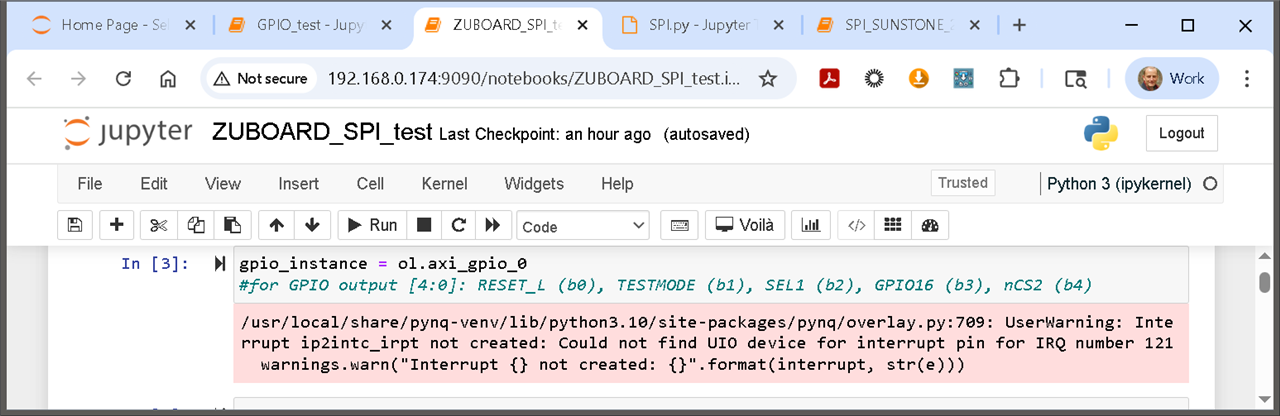
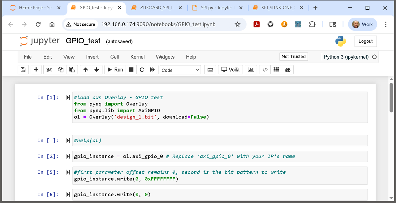
     Even I see the correct PYNQ Python boot log, I can open Jupyter Notebook in web browser, regular Python scripts are working...
     NOT possible to load an overlay (obvious, without FPGA_Manager, not enabled in kernel).

So, at least with a 'correct' BSP (at least version 2022_2) it is possible to see and use the SSD nvme device.
It is also possible to:

  • boot from SD card (as mmc0, the /boot files loaded from SD card)
  • but to mount the rootfs via bootargs to the nvme0n1: root=/dev/nvm0n1
    required to flash the SSD nvme0n1 with the entire rootfs system, e.g. by copying via dd the mmcblk0p2 to the nvme0n1
    (just one partition, for rootfs, no partition for the /boot on SSD: it is anyway not possible to boot from SSD)

So, I can use the SSD as my main file system, running Linux from SSD (SD card just needed for boot).
The SSD is way faster:
the write speed on SSD: >200 MB/s - compared to 20 MB/s on a regular SD card (26 MB/s with the best SD card)

Updated BSP needed:

So, we need just an updated BSP (2022_2, not the original zuboard_1cg.bsp) with the FPGA_Manager enabled (assuming
PCIe support and device tree already enabled in such a newer BSP).
Then we could "patch" the ZUBoard PYNQ image with these two /boot files and it should work (SSD plus FPGA_Manager for
loading overlays in Python).
Actually, the correct way would be to use a newer BSP during the PYNQ build (remark: the buildzu.sh script loads all the time
the original, old BSP from server: we had to modify the build script...).

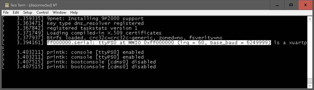
Just: I am struggling to build such a BSP: even I can build it - it crashes on boot:
I seems to configure the UART (for bootlog) with a wrong baudrate and it hangs afterwards.

image

Please,
who could help to generate a newer BSP for ZUBoard, with FPGA Manager enabled?
(e.g. the zub1cg_base_base_2022_2 or this zub1cg_sbc_m2_test_2022_2 "just" plus FPGA_Manager enabled)

  • Sign in to reply
  • Cancel
Parents
  • tjaekel
    tjaekel 1 day ago

    Even with the "patched" PYNQ boot and Jupyter Notebook working, but no FPGA Manager available
    (not possible to load an overlay bit file in Python!),
    you can still load and use an overlay and with Python Jupyter Notebook!

    Just:
    It is not possible to use INT signals, e.g. from a AXI GPIO, with an AXI INTC. As long as your overlay bit file does not have, does not need...
    an INT signal - it still works to load overlay bit file and use it also in Jupyter Notebook.

    Otherwise, you get an error as:
    "could not find UIO device for interrupt pin IRQ 121" or complaining about "ip2intc_irpt not created"

    image

    Not possible to use INT signals in overlay!

    What to do?

    1. copy the overlay bit BITFILE file into folder
      /lib/firmware
    2. change to root:
      su root      (pw is xilinx as well)
    3. create two directories in /dev:
      cd /dev
      mkdir dri
      cd dri
      mkdir by-path
      We do this just to make Python happy (otherwise you get an error about this missing directory path).
    4. still as root:
      echo BITFILE > /sys/class/fpga_manager/fpga0/firmware
      (it is the name of the BITFILE which must be located in /lib/firmware !)
    5. start the Web based Jupyter Notebook:
      use on loading the overlay - which is already loaded, manually, via the step 4 the download=False option:
      from pynq import Overlay
      ol = Overlay("BITFILE.xsa", download=False)
      or:
      ol = Overlay("BITFILE.bit", download=False)
      (you need to have also an associated *.hwh file! and you have created a /dev/dri/by-path directory, otherwise this will fail)

    Now, you can use your (already loaded) BITFILE as regular on PYNQ, even using names for instances, e.g. ol.axi_gpio_o.

    image

    it works: I can toggle the LEDs, implemented in the OVERLAY bit file

    Just using or even having !! INT signals in BITFILE is not possible.
    And always a need to load the BITFILE on UART command line - when changed to root.

    • Cancel
    • Vote Up 0 Vote Down
    • Sign in to reply
    • Cancel
Reply
  • tjaekel
    tjaekel 1 day ago

    Even with the "patched" PYNQ boot and Jupyter Notebook working, but no FPGA Manager available
    (not possible to load an overlay bit file in Python!),
    you can still load and use an overlay and with Python Jupyter Notebook!

    Just:
    It is not possible to use INT signals, e.g. from a AXI GPIO, with an AXI INTC. As long as your overlay bit file does not have, does not need...
    an INT signal - it still works to load overlay bit file and use it also in Jupyter Notebook.

    Otherwise, you get an error as:
    "could not find UIO device for interrupt pin IRQ 121" or complaining about "ip2intc_irpt not created"

    image

    Not possible to use INT signals in overlay!

    What to do?

    1. copy the overlay bit BITFILE file into folder
      /lib/firmware
    2. change to root:
      su root      (pw is xilinx as well)
    3. create two directories in /dev:
      cd /dev
      mkdir dri
      cd dri
      mkdir by-path
      We do this just to make Python happy (otherwise you get an error about this missing directory path).
    4. still as root:
      echo BITFILE > /sys/class/fpga_manager/fpga0/firmware
      (it is the name of the BITFILE which must be located in /lib/firmware !)
    5. start the Web based Jupyter Notebook:
      use on loading the overlay - which is already loaded, manually, via the step 4 the download=False option:
      from pynq import Overlay
      ol = Overlay("BITFILE.xsa", download=False)
      or:
      ol = Overlay("BITFILE.bit", download=False)
      (you need to have also an associated *.hwh file! and you have created a /dev/dri/by-path directory, otherwise this will fail)

    Now, you can use your (already loaded) BITFILE as regular on PYNQ, even using names for instances, e.g. ol.axi_gpio_o.

    image

    it works: I can toggle the LEDs, implemented in the OVERLAY bit file

    Just using or even having !! INT signals in BITFILE is not possible.
    And always a need to load the BITFILE on UART command line - when changed to root.

    • Cancel
    • Vote Up 0 Vote Down
    • Sign in to reply
    • Cancel
Children
No Data
element14 Community

element14 is the first online community specifically for engineers. Connect with your peers and get expert answers to your questions.

  • Members
  • Learn
  • Technologies
  • Challenges & Projects
  • Products
  • Store
  • About Us
  • Feedback & Support
  • FAQs
  • Terms of Use
  • Privacy Policy
  • Legal and Copyright Notices
  • Sitemap
  • Cookies

An Avnet Company © 2025 Premier Farnell Limited. All Rights Reserved.

Premier Farnell Ltd, registered in England and Wales (no 00876412), registered office: Farnell House, Forge Lane, Leeds LS12 2NE.

ICP 备案号 10220084.

Follow element14

  • X
  • Facebook
  • linkedin
  • YouTube