


Introduction
The Azure Sphere MT3620 SoC enables the development of secure, connected IoT devices. Common for these devices is the need to operate in power-constrained environments, eg. on battery power. With careful design, the MT3620 can efficiently be applied in this type of application.
Since the 20.01 Azure Sphere OS release, a "Power Down" MT3620 low power mode has been supported. This turns-off all PMU related power, leaving just the RTC block still running. Two methods to exit this mode are currently supported:
- Wake up after a specified time-period has elapsed
- Wake up when the WAKEUP hardware pin is activated
In this blog, I'll walk you through an example application that demonstrates use of this feature. As support for new low power features gets added, this material will be updated to also exercise those features. Links are provided wherever possible to Microsoft and MediaTek documentation pages, for detailed reference on software and hardware requirements of using MT3620 low power features.
Links
- Power Down: Low power mode for Azure Sphere (I recommend you read this short article now)
- Microsoft article about the power down feature
- Shows the math to power an Azure Sphere device powered by 4-AA batteries for ~2 years, using the Power Down feature
- Nice high level overview of the feature
- MediaTek MT3620 Real Time Clock / Power Down Application Note (I recommend you read this short 10 page Application note now)
- MediaTek application note that contains all the hardware specific details you need to understand and follow when designing an Azure Sphere device that will implement any low power feature
- Microsoft documentation covering MT3620 Hardware implementation for low power features
- This documentation contains much of the same information captured in the MediaTek Application Note
- Azure Sphere Power Down feature documentation
- Microsoft Azure Sphere Documentation on the Power Down feature
- Microsoft documentation on the PowerManagement APIs
- Details about API calls for low power implementations
Required Hardware
To follow along with this blog you'll need the following hardware . . .
- 1 Avnet Azure Sphere Starter Kit
- Product LinkProduct Link
Optional Hardware
I'll be using an Azure Sphere based current measurement system documented in this blog to show power consumed by the device in the different power modes. If you want to measure the current for your device, you'll need to follow along with that blog and have the additional equipment listed below.
- 1 MikroE Power Meter Click Board
- Product LinkProduct Link
- A second Avnet Azure Sphere Starter Kit to collect the measurements
- Product LinkProduct Link
- Momentary Contact Push Button (normally open)
Table of Contents
Hardware Configuration
The Avnet Starter Kit can be used for this example without any changes to the hardware. You do need to identify the WAKEUP signal and an exposed GRD signal on the board if you want to wake the device before the sleep timer has expired.
Identify the signals on the Starter Kit to wake the device from an external source
Remember that once the device is in the Power Down state it can wake up on two different conditions. The first being that a timer expires and the second is that some external input drives WAKEUP low. We want to see this functionality work so let's identify the signals we need to see this feature in action.
The MediaTek application note states . . .
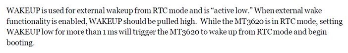
Let's look to see how these connections are implemented on the Avnet Azure Sphere Starter Kit. The Avnet Starter Kit does not pull WAKEUP high (note that R51 is unpopulated), but the Avnet Module does pull WAKEUP high using a 4.7K resistor.
Starter Kit Signals

Avnet Module Signals

So what do we have to do to trigger an external WAKEUP event? It's easy, we just need to connect the WAKEUP signal to GRD for more than 1 ms. This can be accomplished with a jumper wire or my solution I wired a momentary push button switch between WAKEUP and GRD. When my device is in Power Down mode and I want to wake it up, I just push the button!
The most convenient location to find the WAKEUP signal is on the PMOD connector footprint. See the details below from the Starter Kit User Guide.

Here's a photo showing where you can find the WAKEUP signal

My switch plugged into a PMOD connector that I added to my board

You can also just short out the two pins like this photo.

Application Information
Feel free to skip down to the Clone a GitHub Project section if you're eager to keep going. This section describes how we used existing example application to stitch the example application together.
The example includes both a High Level application running on the A7 and a FreeRTOS real-time application running on one of the M4s. The sections below provide the application details. At a high level we leveraged examples and functionality from existing public example repositories and then implemented additional functionality. The goal of this example was to not only show the Power Down feature working, but to create an application base that can be built upon in the future when additional Low Power features are released. The current application will exercise the Power Down logic implemented in the Microsoft Power Down Example. Then using exposed hardware signals, we'll wake our device using an external source, you connecting two signals together.
High Level Application Details
For the High Level application, we started with the Microsoft Azure IoT example and ported in the functionality from the Microsoft Power Down example. Next we pulled in functionality from the MediaTek MT3620_RTApp_FreeRTOS_MBOX example so we could interface with the M4 application.
My colleague rickeycv gets credit for this application. I made a few changes, but it's mostly all Rickey. Rickey has been working on customer Azure Sphere programs for over a year now. Thanks Rickey!
- The high level application was created using the following example applications. The functionality from these examples remains mostly functional in the example.
- Microsoft Azure IoT Example
- Note that Azure connectivity is disabled by default
- To enable Azure connectivity . . .
- Modify build_options.h to enable either IOT_CENTRAL_APPLICATION or IOT_HUB_APPLICTION
- Provide your DPS Scope ID, IoT Hub Hostname, and Azure Sphere Tenant ID
- See the AzureIoT Example for directions on how to setup Azure Services and find the required information for this application
- The example is broken into two different sets of instructions, one for connecting to an IoT Hub and one for connecting to IoT Central.
- To enable Azure connectivity . . .
- Sends simulated temperature telemetry to Azure IoT Central or an Azure IoT Hub at regular intervals
- Sends a button-press event to Azure IoT Central or an Azure IoT Hub when you press button A on the Avnet Starter Kit
- Sends simulated orientation state to Azure IoT Central or an Azure IoT Hub when you press button B on the Avnet Starter Kit
- Controls one of the LEDs on the MT3620 development board when you change a toggle setting on Azure IoT Central or edit the device twin on Azure IoT Hub.
- Note that Azure connectivity is disabled by default
- Microsoft Power Down Example
- Blinks the RGB LED red to indicate the device is awake
- Blinks the RGB LED green to indicate the device is checking for updates or downloading an update.
- A non-blinking green RGB LED indicates updates are ready to install
- Puts the device in the Power Down State for 120 seconds (configurable from Azure)
- Wakes the device from the Power Down state after the timer expires
- Periodically delays putting the device in the power Down state to enable the OS to check for updates
- Restarts the cycle from the beginning after updates (if any) are processed
- MediaTek MBOX example
- We ported the code that sends/receives messages to/from the M4 into this application
- Microsoft Azure IoT Example
- Added functionality
- A7 sends Double Tap telemetry to Azure
- Implemented additional device twins (when connected to Azure)
- SleepTime: Define how long the device Powers Down
- DoubleTapDetection: Enables/Disables Double Tap Detection using the on-board LSM6DS0LSM6DS0 device
- DoubleTapThreshold: Adjustable parameter used for Double Tap Detection
- TimeGapForDoubleTapRecognition: Adjustable parameter used for Double Tap Detection
- QuietTimeAfterATapDetectoin: Adjustable parameter used for Double Tap Detection
- MaximumDurationOfOverThresholdEvent: Adjustable parameter used for Double Tap Detection
- Interfaces with M4 using inter-core communication
- Sends Double Tap configuration parameters to M4
- Receives Double Tap configuration update status
- Receives Double Tap events from M4
- Receives LSM6DS0LSM6DS0 accelerometer data from M4
Real Time Application Details
For the Real Time application, we started with the MediaTek MT3620_RTApp_FreeRTOS_I2C_Accelerometer project and then ported in the Intercore communication logic from the MediaTek MT3620_RTApp_FreeRTOS_MBOX real-time application.
- Added functionality
- Configure the LSM6DSO device to detect Double Tap events
- Allow the A7 to modify the double tap configuration parameters via the M4
- When the M4 detects a Double Tap event it will send a Double Tap message to the A7 and toggle the state of the application LED
Clone the GitHub Project
A couple things to note when you pull this project . . .
- You must clone the git repository from the command line since we need to pass in the --recurse-submodules command line option
- The project needs to be pretty close to the root directory on your drive. If you put the project files too deep into a directory path then the project will not compile and it won't give you any details stating that the path is too long
- Open Windows PowerShell (or your preferred command line shell)
- Change to the directory where you want your project files
- Execute the command: git clone --recurse-submodules https://github.com/Avnet/AVT_LowPower.git

Build and Run the Project
This project will Power Down the device on regular intervals. Because of this behavior, your Visual Studio debug connections will disconnect when the device powers down.
This deployment uses both the A7 and the M4, so we need to build and run two different applications, first the M4 FreeRTOS real-time application and then the A7 High Level application. They need to be loaded in that order, M4 first then A7. This is required because the A7 application will attempt to open a local connection to the M4 and if the M4 application is not running, then the connection will fail and the A7 application will exit.
Build, side-load and run the M4 real-time application
- Launch Visual Studio
- Select the "Continue without code" link

- The Visual Studio IDE will open
- Select File --> Open --> CMake from the pull down menus

- Browse to <your project directory>/AVT_LowPower/RealTimeApp/ and select the CMakeLists.txt file

- The Visual Studio project opens and CMake will generate the build files
- Select the GDB Debugger (RTCore) option from the

- Next build, load and run the real-time application by clicking on the GDB Debugger (RTCore) button

- The application builds, side-loads and runs. You should see the yellow USB activity LED flashing fast on your Starter Kit
- You can see the Double Tap LED indicator toggle if you double tap your device
- If the build fails with an error like the one below, then your path is too long and you need to move your project closer to the root directory on your local drive
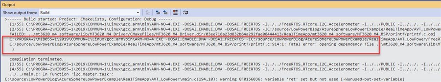
The M4 application is now loaded onto your device. When/if the device shuts down or resets for any reason, the Azure Sphere OS will automatically start the application for you, so we don't need to keep the M4 Visual Studio project open any longer.
Build, side-load and run the A7 High Level application
- Either launch another Visual Studio instance, or select File--> Open --> CMake from the pull down menu from your current Visual Studio instance
- Use the same process that we used with the M4 application to open the project, only this time select the CMakeLists.txt file from <your project directory>/AzureSphereLowPowerExample/HighLevelApp/AzureIoT directory

- Build, side-load and run the High Level project
- Select the "GDB Debugger (HLCore)" target, then click on the "GDB Debugger (HLCore)" button

- The application builds, side-loads and runs
- You should see debug similar to the capture below. Note I generated the Double Tap events by double tapping on my device

Exercise the Solution
Now that both the M4 and A7 applications are running, the device will start the Low Power cycles. You should expect the device to disconnect from your Visual Studio IDE when it goes into Power Down mode.
Expected Behavior
- Application runs for 60 seconds blinking the RGB LED Red
- Application goes into Power Down state for 120 seconds
- The applications will both startup again and either
- Run for 60 seconds blinking the RGB LED Red OR
- Run for 120 seconds checking for an OTA OS or application update from the Azure Sphere Security Service blinking the RGB LED Green
When the device is in Low Power mode you can wake it up before the timer expires by connecting the WAKEUP signal to a GRD signal on the board. See the video below for a demonstration of the application in action.
Power Measurements
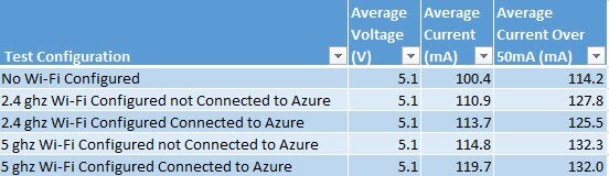
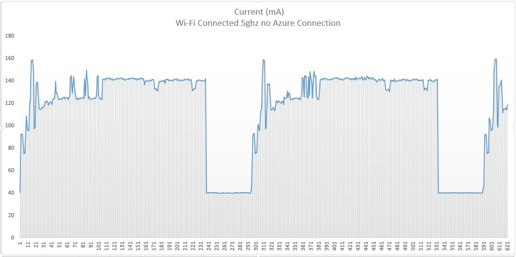
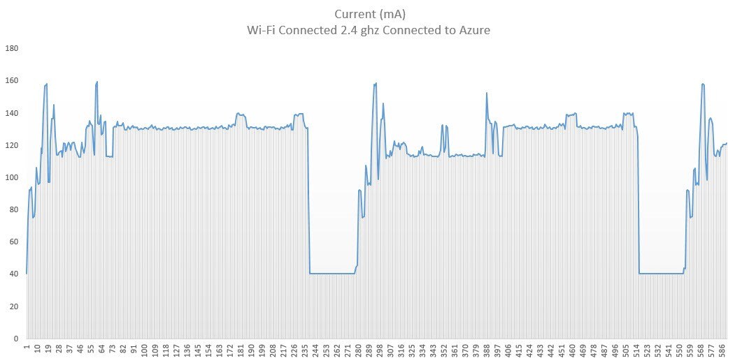
Originally for this section I was just going to measure the power for the simple application to show the current draw of the Avnet Starter Kit executing the Low Power example. I completed that capture, but then got curious about what the power consumption would look like with different Wi-Fi configurations. So I ended up measuring the same application in each of the configurations in the table below. I was a little surprised by the data in this table, I expected the current draw to be a little higher in each of the Azure Connected tests, just because there is data being transmitted. I think if I created an application that hammered the Wi-Fi with data, the average currents would look a little different.
You can really see how when the Wi-Fi is active the current jumps from ~115mA to ~130mA. This is really noticeable in the cases where the application connects to Azure. There is a period at the start of the power-up cycle where the device is maybe crunching on some cryptographic algorithms and the Wi-Fi is held off, then it spikes up.
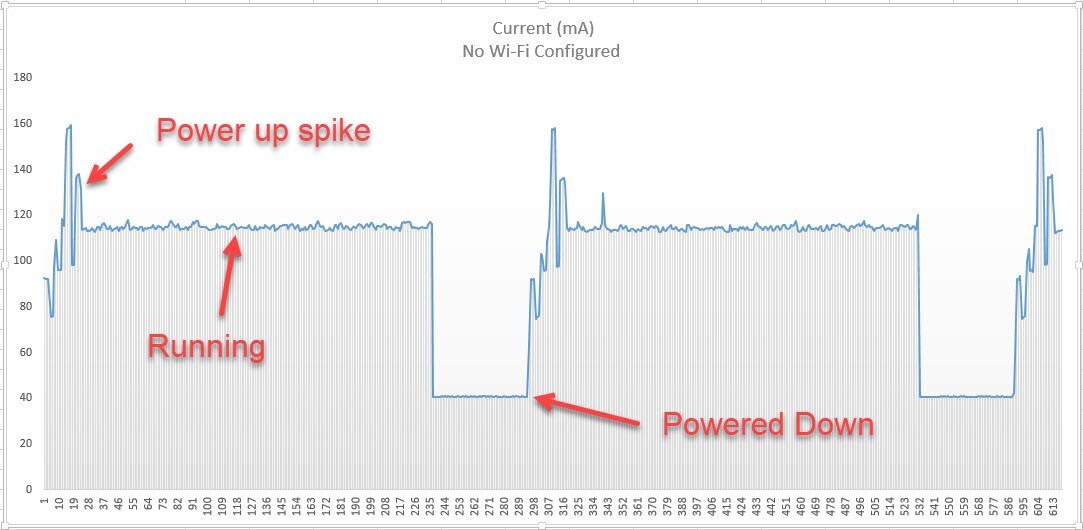
Here are charts for each test. I've added comments to the first graph.


Link to my excel spreadsheet with the data and graphs: Link
A note on the Power Down current draw
You can see in the graphs that in the Power Down state the board is drawing ~40mA of current. The MediaTek documentation states that the MT3620 should be drawing ~0.01 mA. That means that the Starter Kit hardware is consuming most of the 40mA.

Conclusion
Thanks for reading through this Blog. I hope you learned about the current Low Power feature and thought of ways to incorporate this feature into your Azure Sphere based solution. I'm excited to see new Low Power features in the future. When we do, we'll update the reference application and update this blog to help you learn about the new features.
I look forward to your comments and will do what I can to help you if you run into any issues.
Brian
Top Comments