I was there ... sensing citizens recycling.
Introduction
This is an extended version of the project I Was There that I presented at Hackster.io. The version presented in Hackster.io is focused on a solution to issue tokens with a date and time signed by the device. As an example of this solution, I implemented a recycling container that issues tokens to reward citizens who use the recycling container. This extended version is focused on monitoring the uses of recycling bins.
The hackster.io version has a reed switch that allows you to monitor the uses of the container, this new version also incorporates a VCNL4040 proximity sensor with a maximum distance of 20 cm to detect if the container is already full or to detect misuse of it. Likewise, the module's ambient light sensor can detect other anomalies in the container, such as the presence of a flame.
"I was there" creates secure temporary QR tokens (JSON Web Token) signed by an Azure Sphere device for later verification.
The problem
Remotely monitor the uses of recycling bins
The solution
The container has:
- a Reed Switch that detects the door opening and closing.
- a Proximity and Ambient Light Sensor with Infrared Emitter
How does it work
- The user approaches the IWT device.
Then, the user opens the containers door.
- If the device has no message programmed it shows estimate capacity level.
When the door closes the device generates offline a new QR code that contains a signed JWT token, JSON Web Token, including an unique identifier and the date and time of the token issuance.
Then the device displays the QR code on a low power consumption E-Paper display.
Asynchronously, the device sends an event to the Azure cloud in order to:
record and monitor new QR requests
- record times the container is used
- record the internal ambient light in the container
- record the estimate capacity remaining.
The user can capture the image with any camera for later validation or can use a specific application that validates the token at the moment.
After a configurable time the token disappears from the screen and the device is ready to generate the next token.
For loyalty programs the IWT device can issue programmed reward messages from the IOT Central/IOT Hub platform.
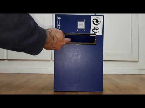
Prototype implementation of IWT for a program of awards to citizens who recycle.
Alternatively, the device may generate an inaudible sound signal that can be recorded with any sound recording device (implementation pending).
My first decision was to try to incorporate a crypto-processor module to perform the encryption, signatures and store the cryptographic keys. Unfortunately, I still did not receive the cryptographic module on time and had to opt for a software solution.
- For cryptography I decided to use the wolfCrypt library. Fortunately wolfSSL released a Visual Studio solution that contains a cryptographic algorithm test for the wolfCrypt library.
- JWT tokens are being formed directly using string functions without using any ad hoc library.
- I have made an adaptation of the STM32 EPD driver for the waveshare 1.54 inch e-Paper Module display.
- I have made an adaption of SparkFun VCNL4040 distance sensor library.
Design
The Hardware
Bill of Materials
| Product Name | Manufacturer | Quantity | Buy KitBuy Kit |
|---|---|---|---|
| AES-MS-MT3620-SK-G - Development Kit, Azure Sphere Starter Kit | AVNET | 1 | Buy NowBuy Now |
| 29A-W - Reed Switch, Standard Gap, 29 Series, 1NO, Surface Mount, 400 mA, 160 VDC, 10 W | GEORGE RISK INDUSTRIES | 1 | Buy NowBuy Now |
| MCMF0W8FF4751A20MCMF0W8FF4751A20 - Through Hole Resistor, 4.75 kohm | MULTICOMP PRO | 1 | Buy NowBuy Now |
Additional Parts
| Product Name | Manufacturer | Quantity |
|---|---|---|
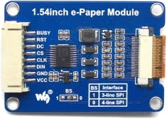
| Waveshare 1.54inch e-Paper Module | Waveshare | 1 |
| SparkFun Proximity Sensor Breakout - 20cm, VCNL4040 (Qwiic) | Spark Fun | 1 |
Schematics
- EPaper display conected in Click 1 (2,3,4,6,7,8).
- Reed Switch conected to PIN GPIO_42, Click 1-1.
- SparkFun Proximity Sensor Breakout - 20cm, VCNL4040 (Qwiic)
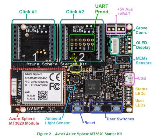
The hardware consists of an Avnet Azure Sphere MT320 Starter Kit development kit and a Waveshare 1.54inch e-Paper Module electronic ink display.
The advantages of Microsoft Azure Sphere solution
Avnet Azure Sphere MT320 Starter Kit
Product LinkProduct Link
- The Azure Sphere MT3620 Starter Kit supports rapid prototyping using Avnet’s certified Azure Sphere module, based on the Microsoft MT3620AN device.
- The MT3620 is the first Azure Sphere certified "micro-controller", a SoC IoT device that features “end-to-end security”.
- User applications can target it's 500 MHz ARM Cortex-A7 core as well as two general purpose 200 MHz ARM Cortex-M4F I/O subsystem cores designed to support real-time requirements. The on-chip peripherals (GPIO, UART, I2C, SPI, I2S, PWM and ADC) can be mapped to any of these three user-accessible cores.
Waveshare 1.54 inch e-Paper Module electronic ink display
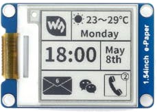
- The electronic ink screen has been chosen for its good qualities to present QR codes and its reduced power consumption in a project of these characteristics.
- It is an E-Ink display module, 1.54 inch, 200 x 200 resolution, with embedded controller, communicating via SPI interface, and supports partial refresh.
- Characteristics: low power consumption, wide viewing angle, clear display without electricity.
1.54inch e-Paper V2 is an Active Matrix Electrophoretic Display (AMEPD), with interface and a reference system design. The 1.54” active area contains 200×200 pixels, and has 1-bit B/W full display capabilities. An integrated circuit contains gate buffer, source buffer, interface, timing control logic, oscillator, DC-DC. SRAM.LUT, VCOM and border are supplied with each panel.
https://www.waveshare.com/wiki/1.54inch_e-Paper_Module
| PART NUMBER | COLORS | GRAY SCALE | RESOLUTION | DISPLAY SIZE (MM) | OUTLINE DIMENSION (MM) | FULL REFRESH TIME (S) | PARTIAL REFRESH | PI HEADER1 | INTERFACE |
|---|---|---|---|---|---|---|---|---|---|
| 1.54inch e-Paper Module | black, white | 2 | 200x200 | 27.60 × 27.60 | 48.0 × 33.0 | 2 | √ | × | SPI |
Interface
| SYMBOL | DESCRIPTION |
|---|---|
| VCC | 3.3V/5V |
| GND | Ground |
| DIN | SPI MOSI pin |
| CLK | SPI SCK pin |
| CS | SPI chip selection, low active |
| DC | Data/Command selection (high for data, low for command) |
| RST | External reset, low active |
| BUSY | Busy status output, high active |
- Different from the traditional SPI protocol, the data line from the slave to the master is hidden since the device only has a display requirement.
- CS is slave chip select, when CS is low, the chip is enabled. (CS#) is the chip select input connecting to the MCU. The chip is enabled for MCU communication: only when CS# is pulled LOW.
- DC is data/command control pin, when DC = 0, write command, when DC = 1, write data. (D/C#) is Data/Command control pin connecting to the MCU. When the pin is pulled HIGH, the data will be interpreted as data. When the pin is pulled LOW, the data will be interpreted as command.
- SCLK is the SPI communication clock.
- SDIN is the data line from the master to the slave in SPI communication.
- (RES#) is reset signal input. The Reset is active low. Note 1.5-4: This pin (BUSY) is Busy state output pin. When Busy is High the operation of chip should not be interrupted and any commands should not be issued to the module. The driver IC will put Busy pin High when the driver IC is working such as: - Outputting display waveform; or - Communicating with digital temperature.
- (BS1) is for 3-line SPI or 4-line SPI selection. When it is “Low”, 4-line SPI is selected. When it is “High”, 3-line SPI (9 bits SPI) is selected.
SPI communication has data transfer timing, which is combined by CPHA and CPOL.
- 1. CPOL determines the level of the serial synchronous clock at idle state. When CPOL = 0, the level is Low. However, CPOL has little effect to the transmission.
- 2. CPHA determines whether data is collected at the first clock edge or at the second clock edge of serial synchronous clock; when CPHL = 0, data is collected at the first clock edge.
There are 4 SPI communication modes. SPI0 is commonly used, in which CPHL = 0, CPOL = 0.
Data transmission starts at the first falling edge of SCLK, and 8 bits of data are transferred in one clock cycle. In here, SPI0 is in used, and data is transferred by bits, MSB first.
Click 1 Pinout diagram
This table shows how the pinout on eINK click corresponds to the pinout on the mikroBUS socket (the latter shown in the two middle columns).
SparkFun Proximity Sensor Breakout - 20cm, VCNL4040 (Qwiic)
https://www.vishay.com/docs/84307/designingvcnl4040.pdf
The VCNL4040 is a fully integrated proximity and ambient light sensor. It combines an infrared emitter and photodiode for proximity measurement, ambient light sensor, and signal processing IC in a single package with a 16-bit ADC. The device provides ambient light sensing to support conventional backlight and display brightness auto-adjustment, and proximity sensing to minimize accidental touch input that can lead to call drops and camera launch.
With a range of up to 20 cm (7.9"), this stand-alone component greatly simplifies the use and design-in of a proximity sensor in consumer and industrial applications, because no mechanical barriers are required to optically isolate the emitter from the detector.
- Qualitative Detection Range: 20cm
- Integrated Modules: Infrared Emitter (IRED), Ambient Light Sensor (ALS), Proximity Sensor (PS)
- Operates ALS and PS in Parallel Structure
- No Dead Zone
- Operating Voltage: 3.3V
- I2C Address: 0x60
- 2x Qwiic Connectors
Click 2 Pinout diagram
This table shows how the pinout for the VCNL4040 Proximity Sensor corresponds to the pinout on the mikroBUS socket (the latter shown in the two middle columns).
| Notes | Pin |  | Pin | Notes | |||
|---|---|---|---|---|---|---|---|
| NC | 1 | AN | PWM | 16 | NC | ||
Interrupt output GPIO17 | RST | 2 | RST | INT | 15 | INT | |
| NC | 3 | CS | RX | 14 | NC | ||
| NC | 4 | SCK | TX | 13 | NC | ||
| NC | 5 | MISO | SCL | 12 | SCL | I2C Clock SCL2 | |
| NC | 6 | MOSI | SDA | 11 | SDA | I2C Data SDA2 | |
| Power Supply | 3.3V | 7 | 3.3V | 5V | 10 | NC | |
| Ground | GND | 8 | GND | GND | 9 | GND | Ground |
Reed Switch and Magnet
The magnet is behind the door.
The circuit is closed when a magnet is near the switch, indicating the opening is shut. Opening the door breaks the connection.
Sensing the user
In addition to launching the new QR code when the button is pressed, we can activate it when it detects when the user using the recycling container using a proximity sensor.
- The reed switch we'll be using is normally-open. We have two alternatives to detect when the door is fully closed o when the door is fully opened. For this project we will be using the first alternative:
- Detect door fully closed: The magnet is close the Reed Switch when the door is closed and will be in that state until the door is opened. We connect the Reed Switch to ground and we will pull up the GPIO pin 42 via 4.7K. In closed stated will read Low. The event for a new QR will be sent when passing from High to Low, that is when the door is fully closed again, rewarding the user for closing the door
 after use.
Sensing the container capacity
Inside the container a Proximity sensor allow us to estimate the remaining capacity of the container.
Software Design
State Diagram
- Idle show the "Press A"
- Rewards show reward associated to the QR if any
- JWT_QR issue and show new QR Token
- Clock show time clock
- Settings show settings
- Synch Settings sync settings with Azure cloud
- Azure Cloud Async Tasks send/receive/synch cloud data
User Interface
Using the Reed Switch to detect door opening and closing:
When the door is open Cloud Programmed message is displayed.
When the door is closed a new JWT QR is issued and displayed during a programable delay.
Using the A Button:
- When the A Button is pressed the Cloud Programmed message is displayed.
- When the A Button is released a new JWT QR is issued and displayed during a programable delay.
| {gallery} User Interface |
|---|
Idle Screen: During the Idle state the screen shows the indication of pressing the A button to obtain a new QR |
Rewards Screen: Once button A has been pressed if a new prize status was received for the next QR, the prize associated to the QR is displayed. Option for customer loyalty programs. |
QR Screen: Then the new QR code containing a signed JWT token. A time set from the Azure cloud will be in this state. |
Clock Screen & Settings: When the B button is pressed, a clock with the current time of the device is displayed and if pressed again the application settings are displayed. |
Source Code
Github Repository
I-Was-There https://github.com/javagoza/I-Was-There
C Code for Azure Sphere Platform. Use Git or checkout with SVN using the web URL. wolfssl library it is not included.
You will also need to clone WolfSSL library under wolfssl folder
Configuring your hardware and libraries
WolfSSL Settings
Build Options
Epaper PIN definition
Reed Switch
#define AVT_MODULE_GPIO42_ADC1   MT3620_GPIO42
#define AVT_SK_CM1_AN AVT_MODULE_GPIO42_ADC1
#define PROXIMITY_GPIO AVT_SK_CM1_AN
PIN Defines
#define AVT_MODULE_GPIO31_SCLK1_TXD1 (GPIO_Id)31
#define AVT_MODULE_GPIO32_MOSI1_RTS1_CLK1 (GPIO_Id)32
#define AVT_MODULE_GPIO33_MISO1_RXD1_DATA1 (GPIO_Id)33
#define AVT_MODULE_GPIO34_CSA1_CTS1 (GPIO_Id)34
#define EPAPER_DC (GPIO_Id)0
#define EPAPER_BUSY (GPIO_Id)2
#define EPAPER_RESET (GPIO_Id)16
#define EPAPER_SCLK AVT_MODULE_GPIO31_SCLK1_TXD1
#define EPAPER_MOSI AVT_MODULE_GPIO32_MOSI1_RTS1_CLK1
#define EPAPER_CS AVT_MODULE_GPIO34_CSA1_CTS1
Samples that demonstrate SPI functionality on the Azure Sphere platform:
https://github.com/Azure/azure-sphere-samples/tree/master/Samples/SPI
Creating the JWT Token QR
Anatomy of the JWT Token QR
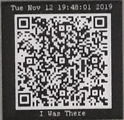
The device will use QR codes like the one in the nest image:
The QR code contains this string:
eyJhbGciOiJIUzI1NiIsInR5cCI6IkpXVCJ9
.eyJqdGkiOiJlMmRhNzc3My1hN2NkLTQ0YTAtODVkNy00M2ZlMDY1NGNiMjItN2RjNTQ4MTEtNWRjYjBjNzAiLCJpYXQiOjE1NzM1ODgwODB9
.Dm8qKzv5n0EHMCcIECn08Ev_eppzPNc-hGtuICCNGK0
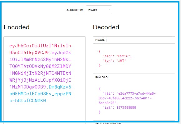
It is a JSON Web Token in its compact form. A JWT typically looks like the following: xxxxx.yyyyy.zzzzz
- JSON Web Token (JWT) is a compact, URL-safe means of representing claims to be transferred between two parties. JSON Web Token (JWT) is an open standard (RFC 7519) .
- The claims in a JWT are encoded as a JSON object that is used as the payload of a JSON Web Signature (JWS) structure or as the plaintext of a JSON Web Encryption (JWE) structure.
- This information can be verified and trusted because it is digitally signed.
- JWTs can be signed using a secret (with the HMAC algorithm) or a public/private key pair using RSA or ECDSA. https://tools.ietf.org/html/rfc7519
It consists of three parts separated by dots (.), which are:
- Header: contains the metadata for the token and it minimally contains the type of signature and the encryption algorithm.
- Payload/Claim: contains the information we want to transmit,
- Signature: calculated using the header and the payload, you can also verify that the content hasn't been tampered with.
Contents of the three parts are Base64Url encoded. Decoding the three parts of the above token:
{ "alg": "HS256", "typ": "JWT" }
- iat: “Issued at” time, in Unix time, at which the token was issued
- jti: JWT ID claim provides a unique identifier for the JWT
{
"jti": "e2da7773-a7cd-44a0-85d7-43fe0654cb22-7dc54811-5dcb0c70",
 "iat": 1573588080
 }
HMACSHA256( base64UrlEncode(header) + "." + base64UrlEncode(payload), [your-256-bit-secret] )
Securing the JWT Token
wolfSSL
Keyed hash hmac
Generating the QR Code
- Stack-based (no heap necessary; but you can use heap if you want)
- Low-memory footprint (relatively)
- Compile-time stripping of unnecessary logic
- MIT License;
https://github.com/ricmoo/QRCode
Going to Cloud
Implementation steps:
- Create a custom IoT Central application
- Create a device template
- Add QR Request events to the Measurements Tab
- Add Toggle controls to the Settings Tab: RGB LED controls, WWAN and APP LED controls
- Add Application information to the Properties Tab
- Application Version
- Current SSID
- BSSID
- Current Wi-Fi Radio Frequency
Resources
Monitoring Container
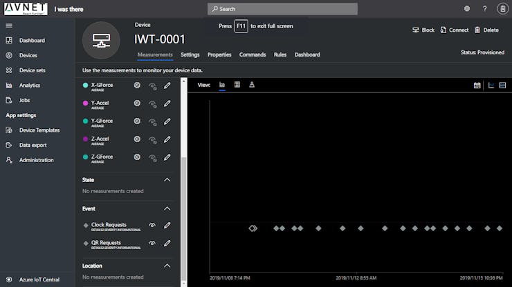
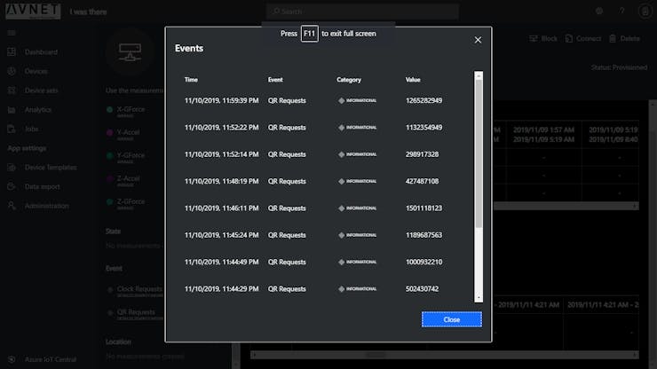
- Whenever a new weekly QR code is issued asynchronously an event to the Azure cloud, either to Azure IoT Central or to Azure IoT Hub as the application was built.
- The points seen in the next image correspond to events of QR code generation after pressing the A button or when the reed switch detects a step from open to closed.
- We can see a detailed list view of the events with the generated QR ID.
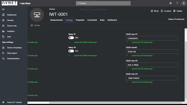
- New award or information messages can be programmed from IoT Central or completely disabled.
Development tools
Work attribution:
- wolfSSL-wolfCrypt: The wolfCrypt cryptography engine is a lightweight crypto library written in ANSI C and targeted for embedded, RTOS, and resource-constrained environments. https://www.wolfssl.com/products/wolfcrypt-2/
- Richard Moore: QRCode - A simple library for generating QR codes in C, optimized for processing and memory constrained systems. https://github.com/ricmoo/QRCode
- waveshare :1.54inch e-Paper V2 STM32 demo code: https://github.com/waveshare/e-Paper/tree/master/STM32/STM32-F103ZET6
- Peter Fenn & Brian Willess, (Avnet Engineering & Technology).: The awesome Avnet Azure Sphere Starter Kit Reference Design Team https://github.com/Avnet/AvnetAzureSphereStarterKitReferenceDesign
- Sparkfun : Arduino library for the VCNL4040,: https://github.com/sparkfun/SparkFun_VCNL4040_Arduino_Library
This my device: Fullcarga1






Top Comments