The secure environment provided by Azure Sphere can be used to secure valuables or initiate alarms when sensing anything wrong.
Things used in the project.
- AVNET Azure Sphere
- External power bank
- Microsoft Visual Studio 2019
- Microsoft Azure Sphere SDK
The Problem
Today privacy matters a lot especially for teenagers. Someone visiting your house can open your cupboard filled with valuable without your knowledge. It maybe your friends, relatives and your own brother or sister. Your valuables may contain anything like your coin collection or some personal things which you don't want anybody to have a look at. And if you have a friend from security probably, he could hack in the system. I have 2-3 friends specialized in security so using a regular IoT hardware in my wardrobe is not worth my privacy.
The Solution
Why Azure Sphere, Its secure and reliable!
Introduction to technologies used -
- Defense in depth provides multiple layers of protection to help guard devices against and respond to threats.
- Deployment flexibility helps you secure existing equipment and build protection into new IoT investments.
- Over-the-air (OTA) updates make it easy to add new features and improve performance throughout device life-cycles.
- Error reporting and automatic security updates help you stay ahead of new and evolving threats.
- Azure Sphere–certified chips from our hardware partners have built-in Microsoft security technology to provide connectivity and a dependable hardware root of trust.
- Azure Sphere OS adds layers of protection and ongoing security updates to create a trustworthy platform for new IoT experiences.
AVNET Azure Sphere MT3620 Starter Development Kit (Carrier Board)
Starter Kit highlights Avnet's certified, production-ready Sphere MT3620 module which is based on the highly integrated MediaTek MT3620AN tri-core Wi-Fi SoC device. Embedded user applications targeting it’s 500 MHz ARM Cortex-A7 application processor are built and debugged using Microsoft’s popular Visual Studio IDE.
The SoC also includes two 200 MHz ARM Cortex-M4F MCU cores to meet real-time I/O requirements, plus a rich variety of on-chip peripherals (GPIO, UART, I2C, SPI, I2S, PWM, ADC) that can be assigned to any of the three processor cores. The kit includes: A carrier board with Azure Sphere MT3620 module, USB cable, and Quick Start Card.
Hardware Specs
Based on the MT3620AN SoC
- 1x 500MHz ARM Cortex A7, 4MB SRAM
- 2x 200MHz ARM Cortex M4F cores, 64KB SRAM
- Dual-band 2.4/5GHz 802.11 a/b/g/n WiFi
Module I/O peripheral support
- 3x ISU interfaces pre-configured for UART, SPI, I2C
- ADC/GPIO: 3x 12-bit ADC inputs (or 3 GPIOs)
- PWM/GPIO: 9x PWM outputs (or up to 24 GPIOs)
- RTC (requires VBAT supply)
- Programming & recovery Interface
Chip antenna version
- Dual-band 2.4/5GHz chip antenna (Pulse W3006)
- Operating Temperature: -30~85°C
Dimensions: 33mm x 22mm x 3mm
Microsoft Azure
Microsoft Azure is a cloud computing service created by Microsoft for building, testing, deploying, and managing applications and services through Microsoft-managed data centers It provides software as a service (SaaS) platform as a service (PaaS) and infrastructure as a service (IaaS) and supports many different programming languages, tools and frameworks, including both Microsoft-specific and third-party software and systems.
Azure IoT Central
Azure IoT Central is a fully managed global IoT SaaS (software-as-a-service) solution that makes it easy to connect, monitor and manage your IoT assets at scale.
An IoT app platform that reduces the burden and cost associated with developing, managing, and maintaining enterprise-grade IoT solutions. Choosing to build with Azure IoT Central gives you the opportunity to focus your time, money, and energy on transforming your business with IoT data, rather than just maintaining and updating a complex and continually evolving IoT infrastructure.
The easy-to-use interface makes it simple to monitor device conditions, create rules, and manage millions of devices and their data throughout their life cycle. Furthermore, it enables you to act on device insights by extending IoT intelligence into line-of-business applications.
How to implement guide -
- Setup AVNET Azure Sphere Starter Development Kit
- Run basic blink program for verification
- Setup Microsoft Azure Cloud Account
- Setup Azure IoT Central to work with Azure Sphere
- Setting up rules to trigger email
- Cloud deployment of application for security
- Final placement of the Module on your wardrobe/cupboard door
1. Setup AVNET Azure Sphere MT3620 Starter Development Kit
Its highly recommended to follow the Microsoft documentation. Follow the documentation for all sort of troubleshooting.
If you face any problems regarding sudden shutdown of device or some SDK issue check out this Element14 Blog. Or ask in Element14 Azure Sphere Group.
Prerequisite's before starting the project.
- Followed the Microsoft Azure Sphere Documentation for installation.
- Finished setting up Azure Sphere SDK and Visual Studio.
- Confirm that your device is connected to your PC using the supplied USB cable.
- From the Azure Sphere CLI from the start menu then enter the command
azsphere login--newuser <azure-email-address>. - Create a tenant, enter this command
azsphere tenant create --name <my-tenant> - Claim your device use this command
azsphere device claim - Add a Wi-Fi network to your device.
azsphere device wifi add --ssid <yourSSID> --psk <yourNetworkKey>To check use this commandazsphere device wifi show-status
You have successfully setup your Azure Sphere its as easy as that.
2. Run basic sensor program on your Azure Sphere for verification
The basic sensor application is copied from Azure Sphere Out of the Box part 1.
- Put your device to debugging mode. Use command
azsphere device enable-developmentorazsphere dev edv(make sure you have connected your device and its working.
The basic sensor program is going to show the following.
- Determine the BSSID address, Wi-Fi AP SSID and Wi-Fi Frequency.
- Read X, Y, Z accelerometer data from the onboard LSM6DSO device using the I2C Interface.
- Read X, Y, Z angular rate data from the onboard LSM6DSO device using the I2C Interface.
- Read the temperature from the onboard LSM6DSO device using the I2C Interface.
- Read the barometric pressure from the onboard LPS22HH device using the I2C Interface.
- Read the temperature from the onboard LPS22HH device using the I2C Interface.
- Read the state of the A and B buttons.
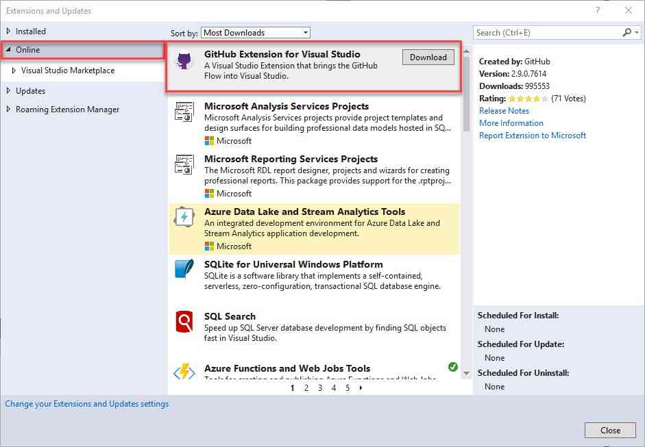
Now that we have the GitHub extensions installed we can clone the project to our local drive.
- Open Visual Studio, Start a blank project without any code. From the pull down menus select "File" then select “Clone or check out code”. In the repository location paste this
https://github.com/Avnet/AvnetAzureSphereStarterKitReferenceDesign.git
This cloned project has three different build configurations
- No cloud connectivity. This is the simplest configuration. The application runs and you can monitor sensor data from the Visual Studio debug window.
- IoT Hub connectivity. This configuration requires an Azure IoT Hub and an IoT Hub connection string. Once we have the Hub configured and the application connecting to the IoT Hub, we'll explore device twins and learn how we can use device twins to make application changes from the cloud. Last, we’ll walk through how to provision a Time Series Insights (TSI) application to visualize the sensor data.
- IoT Central connectivity. This configuration leverages Microsoft’s IoT Central SaaS product. IoT Central provides a simple interface that allows users to visualize telemetry and to control connected devices.
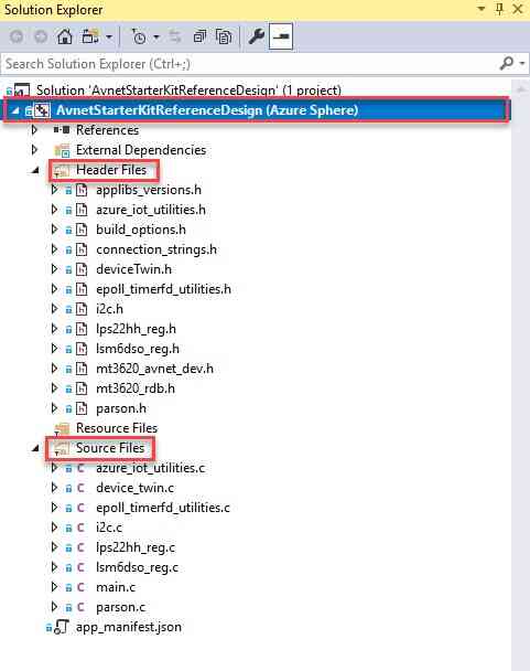
Open the Solution Explorer and expand the project “AvnetStarterKitReferenceDesign” This will display all the different resources in the project. Expand the “Header Files” and “Source Files” folders to see the source code for the project.
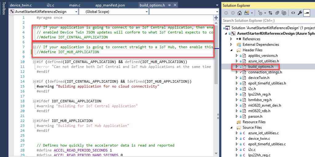
The build configurations are defined in the build_options.h file. Open that file and confirm that both IOT_CENTRAL_APPLICATION and IOT_HUB_APPLICATION are both commented out. Look around lines 5-8 for the #define pre-processor directives. This will build the no cloud connectivity configuration.
One of the really cool features of the Azure Sphere development environment is that to build, link, load, and run your embedded application all you have to do is click one button.
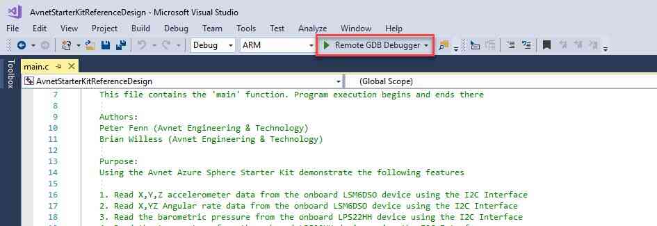
- Build, link, sideload, and run the project by clicking on the “Remote GDB Debugger” button at the top of the application.
You’ll see the build and link process, then a popup window stating that Visual Studio is starting the debugger on the target. If all goes well, you should see output similar to the text below. If there is a problem, the build output will tell you what’s wrong and hopefully provide a hint on how to correct the issue.
Remote debugging from host 192.168.35.1
Version String: Avnet-Starter-Kit-reference-V1.0
Avnet Starter Kit Simple Reference Application starting.
LSM6DSO Found!
LPS22HH Found!
LSM6DSO: Calibrating angular rate . . .
LSM6DSO: Please make sure the device is stationary.
LSM6DSO: Calibrating angular rate complete!
Opening Starter Kit Button A as input.
Opening Starter Kit Button B as input.
SSID: AvnetIOTDEMO
Frequency: 2462MHz
bssid: 00:15:ff:7d:a8:5f
LSM6DSO: Acceleration [mg] : 62.8300, -36.9660, 1002.7180
LSM6DSO: Angular rate [dps] : 0.00, 0.00, 0.00
LSM6DSO: Temperature [degC]: 24.11
LPS22HH: Pressure [hPa] : 1063.18
LPS22HH: Temperature [degC]: 23.08
You have successfully completed your first demo application well done! Now you are good to go for the next application that is our PROJECT.
3. Setup your Microsoft Azure Cloud Account
For using Azure you need to have a account. You can get one free here. But you may need a credit card.
THANKS TO GITHUB for providing Student pack this gives you access to a huge variety of developer tools which are paid for regular users.
But if you are a student with no credit card and coming form a not known college like me then sign up for a GitHub Student Developer Pack.
For this all you need is a valid college ID card. You may have to wait for a week or 2 for a verified GitHub account. After you get access to student pack search for Azure offer they would provide with a 25 digit verification code and sign up here.
4. Setup Azure IoT Central to work with Azure Sphere
I have added many extra telemetry events for you to thinker around, you can remove them if you feel like. Only gryoscope telemetry data is needed for this project
- Now login to your Azure account
- Create a IoT Central Application here, if the link doesn't work simply search for IoT Central Application in the Azure Home search bar and create / + one.
- Fill in suitable information. As you are new to Azure you may have to create a new resource group, So click create new and fill the required info there. Now select "Custom Application" under Template.
- Now "Create" the application. It make take a couple of minutes.
- Now directly go to your Application URL previously defined in the application form.
xxxxx.azureiotcentral.comreplace xxxxx with your custom URL. If you cant access the URL, search for IoT Central Application in your Azure search bar.
- Find you application and open it. And then go-to your IoT Central URL shown there.
- Here you’ll see the landing page. The first thing we need to do is to create a “Device Template,” so click on the link at the left side of the page.
A device template is where we’ll define all the information that will be displayed for our device. By default there are not any templates for our beloved Azure Sphere. On the “Device Templates” page, find the “+” link at the top right and click.
You’ll be given many choices to start your new template.But select the “Custom” square as there isn't any AVNET Azure Sphere Template predefined.
Enter a name for your template, then click on the “Create” button.
The next page shows your new template. The template is empty. So let’s build it out! We’ll add Telemetry data first, so click on the “+ New Measurement” link.
On this page you can add different things to your template. Telemetry, State or Events. The first thing we’ll do is configure some telemetry items, so click on the “Telemetry” square.
This is where we define all the properties for a new Telemetry item. We’re going to add the X G-Force component to the measurement data graph. To do this we just need to fill out the form.
- Display Name: The name of the telemetry item to add (anything you want)
- Field Name: Enter the “key” name of the {“key”: value} key pair telemetry data. The sample Azure Sphere application uses “gX” for the X g-force component, so we enter “gX” in this field.
- Units: Anything you want, but it should represent the units of your telemetry data, in our case milli-g-force so “mG”
- Min/Max Value: Use these fields to add bounds to your graph. You should select values that are close to what you expect the maximum and minimum values to be. That way your graph will not have too much empty space or allow your data to be off the graph. We'll set our limits in the range (-1500, 1500)
- Decimal Places: How many decimal places to show on your graph, I selected to display 3 decimal places of accuracy.
- Color: Select the color you want for this telemetry item
- That’s all there is to add telemetry data. The critical piece is that you need to know what key:value pairs your application is sending up. Once you fill out the form, click on the “Save” button at the top of the form.
- Next we need to add Telemetry entries for other axis. Use the table below and your new knowledge to add rest of the data.
Angular Rates and Pressure
After entering the telemetry measurements, your screen should look similar to the picture below.
- You may notice data showing up in the graph already. This data is being generated by a Simulated Device. Whenever you create a new Device Template in IoT Central it will auto generate a simulated device, and that device will start to send random data within the min/max bounds you defined in the new measurement configurations.
- To manually add a device to IoT Central, navigate to the Device Explorer by clicking on Device Explorer.
- Once you’re in the Device Explorer you’ll see the simulated device that was automatically created for you and no other devices listed.
- Add a new “Real” device by clicking on the “+” link and selecting “Real.”
This will open the “Create New Device” form.
- Device ID: Leave this set to the default.
- Device Name: This field is pre-populated with the device template name and the device ID. I like to change it to something friendly.
Click the “Create” button.
Once created, you’ll be taken to the new devices main page. There’s nothing interesting here yet, because our device is not yet connected to the application. The next step is to generate the connection string.
To generate the connection string we’ll use a tool called dps-keygen. This is a simple command line tool where you provide specific information about your IoT Central application and your device, and the tool generates a connection string that your application can use to connect to IoT Central.
Note: node.js must be installed to run the dps-keygen utility. Node JS can be installed here: https://nodejs.org/en/
- From Windows Powershell execute the command
npmi -g dps-keygen. You should see output similar to the picture below:
- Navigate to your “real” device and click on the Connect link at the top right.
The “Device Connection” dialog box contains all the details we need to use the dps-keygen utility. We need Scope ID, Device ID, and Primary Key.
- Notice that Microsoft provides a link at the right side to copy the contents into the copy/paste buffer.
- Back in Windows PowerShell use the dsp-keygen utility to generate the connection string. The command is
dps-keygen -si:<scope ID> -di:<device ID> -dk:<device primary shared key>
Note: Make sure you don't have any spaces between the command line arguments and their value. For example do NOT have any spaces between the -si: switch and the scope ID you provide for the -si option
- Using my device details it looks like this:
My connection string is: HostName=iotc-asdjfnalkejmnfkawjenasjdfnlsamdnfazure-devices.net;DeviceId=asdjfnalksejmnfajenfkasjdnflkmwenawen;SharedAccessKey=skdjfnadjfnkajsdnflkajsdnfkjasdcnfuwejadnfasdfasdkjfas
- Now let’s go back to Visual Studio. If it’s not open, go ahead and launch the Visual Studio application and open the “AvnetStarterKitReferenceDesign” project. Visual Studio keeps a list of recent projects, your project should be found in that list.
- Open the
build_options.hfile - On line #5 remove the “
//” comment characters to enable the#define IOT_CENTRAL_APPLICATIONconfiguration.
- Open
connection_strings.hand paste the connection string you generated with the dps-keygen tool inside the “ ”. The entry in my file looks like this:
Notice that the first part of the string contains a FQDN hostname, in my case, the hostname is “akjwenflksandklfaneiqanwefijazure-devices.net”
- Open the
app_manifest.jsonfile. This file is located outside the other folders in your Solution Explorer window, usually at the very bottom of the list. - Find the “
AllowedConnections” entry and paste the hostname from your connection string into the field with a set of “ ” around the text. If you already have a FQDN for your IoT Hub example, you can replace this FQDN, or add to the list by comma separating the two entries.
- To compile, link and load the application onto your Starter Kit, you just need to click on the “
Remote GDB Debugger” button in the toolbar.
You’ll see the build process run and a popup box stating that Visual Studio is starting the application. If you look at the output window, you should see something similar to the text below.
Check out your Azure IoT Central Application select real device which you created later, you will find telemetry data there.
NOTE: Azure UI may change overtime so just use you brains to guess things and work around!
5. Setting up rules to trigger email
- Now navigate to your template and select the rules tab.
- Click on "+ New", We are going to create the most important rule now. The event which would trigger the email stating that your cupboard isn't safe!
- Select telemetry
Fill out the required information
Create other two conditions like shown below
Save and click on Actions + and select Email
Fill in the email information the way you like it.
- Click on save you have successfully created a event for movement alert you have completed the main part.
6. Cloud deployment for security
Right now your application is in Debugging mode that is it can be accessed by other to destroy or create an issue with the device we are going to change from deployment stage to field test stage which is almost like production stage but not for consumers.
Follow the commands carefully
- Create a product
azsphere product create --name MyProduct - Enable Cloud based deployment
azsphere device enable-cloud-test --productname "MyProduct"
- Find the
.imagepackagefile. Go to your previously cloned GitHub repo on your local disk. GoAvnetStarterKitReferenceDesign > bin > ARM > Debug > AvnetStarterKitReferenceDesign.imagepackage. Copy this path.
- Load image to your azure sphere device
azsphere device-group deployment create --devicegroupname "Field Test" --productname MyProduct --filepath path\to\AvnetStarterKitReferenceDesign.imagepackage
- Now just unplug your device and connect it to a 5v-2A wall charger or power bank and click on reset button on the board. GREAT now you can see the telemetry on your computer, just move or shake your azure sphere after some time you will recive some
7. Final Placement of module on your wardrobe / shelf door
Hiding my Azure Sphere Movement Detection Module inside a perfume box. And placing it just behind the door.
Note :
- Azure UI and links may change overtime so do some google searches or ask in forums like Element14 Azure Sphere. Guys here are super helpful!
- All the
azspherecommands are based on SDK 19.10. After further update some commands may change. - Sorry for low quality videos and images, at time I didn't have access to high quality capture devices.
- Many of the content was copied from Azure Sphere Out of the box demo


_wryIlE9LrJ.png)


