- How to begin, system architecture
- Pin Mapping of a Xilinx Device
- Defining Chip Sets used
- What meets your system Architecture design
- Todays Chip Challenges, putting this as a top priority
- Order Now!
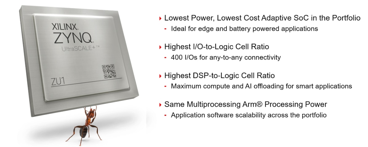
When beginning your system architecture, you must reflect upon your goals and desired functionality of the board. This development kit begin low cost, we decided on selecting the smallest MPSoC chip in the Xilinx portfolio. We selected the MPSoC ZU+ 1CG A484 MPSoC device. This is a relatively new device in today’s market focused on lower power and high compute applications. This device features Dual ARM Cortex-A53 cores, Dual Arm Cortex-R5F cores, and FPGA fabric. This is a critical step in defining your system architecture as it directly affects all peripheral sets to some degree. For instance, in the ZU+ 1CG A484 MPSoC device we are limited to the following:
- 170 Processing System IO (PS MIO & DDRIO)
- 24 High Density IO
- 58 High Performance IO
- 4 PS transceivers

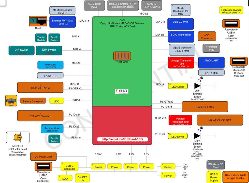
With these IO limitations we began our peripheral selection and evaluated it from a cost and functional perspective. In our selection we settled on the following peripheral set.
- PS Subsystem
- Battery Backed Real Time Clock
- Boot Mode Slide Switch
- PS DDRIO
- 1GB LPDDR4
- PS MIO
- Gigabit Ethernet
- USB 2.0 Host
- 256Mb Serial NOR Flash Boot
- uSD Card Boot Method
- On-board JTAG & UART
- LEDs
- User Slide Switches
- Pressure Sensor
- SYZYGY transceiver expansion site
- HD I/O
- Temperature Sensor
- MikroElektronika Click Site
- SYZYGY Transceiver Site
- HP I/O
- SYZYGY Standard Site
- SYZYGY Transceiver Site
We chose this peripheral set to enable the basics of customer enablement and maximum flexibility at a low cost. We have wired ethernet connectivity and a standard set of peripherals such as the USB 2.0 interface, LED and Switched IO, and sensor data. This provides a standard IoT enabled application out of box to enable engineers. In addition, we have the three SYZYGY sites and Click board site to enable high and low speed application through add-on boards. These add-on sites also lower the cost of the basic platform as it takes the extended functionality off board providing maximum flexibility for customer application development.

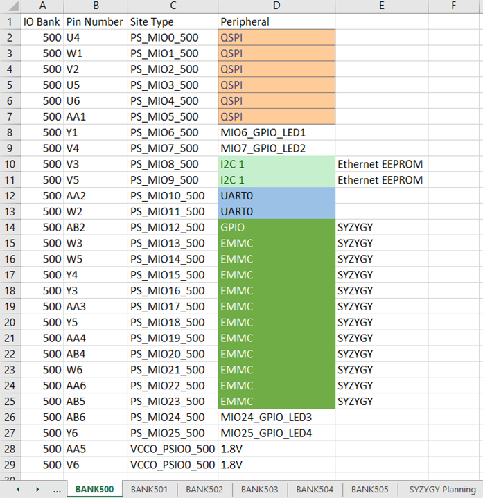
To complete this functional validation, it involved a large excel sheet in which I would evaluate the desired functionality against the working Vivado block design and the MPSoC TRM UG1085. On the excel sheet I would have a pin description for each I/O and I/O Bank. Next to that description would be the desired functionality at the desired I/O voltage. This was a puzzle in making maximum usage of the PL and PS I/O as I’d verify it against the block design in Vivado to make sure there are no conflicts. From the TRM perspective you would need to verify pin functionality capability. For instance you need to identify any clock capable PL pins for desired functionality and also desired boot method pins for your SD Card eMMC, and QSPI interfaces.

Now that the basic functionality has been defined, we need to determine each chipset we want to use to enable these functionalities. There are a few driving factors in component selection in today’s market. At the top of the list is when it comes to device selection is availability. The worst thing you could do is choose a part that isn’t available for 2 years which would in turn either delay your project significantly or cause you to redesign your production unit. In addition to identifying available components, you need to be proactive in your ordering of the desired chipsets. You really need to work with your purchasing department in regard to getting them on order for your production build as soon as they are identified. In a few instances we were required to switch component selection due to not ordering the desired component in time. In some instance the desired components were sold within 3 days of identifying them.
In additional to availability, you want to identify components that meet your desired specification and life cycle. Designing in a component that will be EOL in 1 year is never a good idea, so identify manufacturers that offer some longevity program for their components. In addition, verify your specification is met, for instance if you spec a Gigabit Ethernet PHY but choose a 10/100 Ethernet PHY, you’re going to have a bad time. The same goes for verifying any expansion connector interfaces identified can operate at the desired maximum operating speeds.
With these items in mind then now expand on using Altium for schematic capture and the various challenges faced. Tune in for blog #3.
Link to Blog #1 - /products/devtools/avnetboardscommunity/b/blog/posts/zuboard-1cg-1-defining-a-product-in-today-s-market
Link to Blog #3 - /products/devtools/avnetboardscommunity/b/blog/posts/zuboard-1cg-3---getting-started-with-schematic-capture
