element14 Community
element14 Community
    Register Log In
  • Site
  • Search
  • Log In Register
  • Community Hub
    Community Hub
    • What's New on element14
    • Feedback and Support
    • Benefits of Membership
    • Personal Blogs
    • Members Area
    • Achievement Levels
  • Learn
    Learn
    • Ask an Expert
    • eBooks
    • element14 presents
    • Learning Center
    • Tech Spotlight
    • STEM Academy
    • Webinars, Training and Events
    • Learning Groups
  • Technologies
    Technologies
    • 3D Printing
    • FPGA
    • Industrial Automation
    • Internet of Things
    • Power & Energy
    • Sensors
    • Technology Groups
  • Challenges & Projects
    Challenges & Projects
    • Design Challenges
    • element14 presents Projects
    • Project14
    • Arduino Projects
    • Raspberry Pi Projects
    • Project Groups
  • Products
    Products
    • Arduino
    • Avnet Boards Community
    • Dev Tools
    • Manufacturers
    • Multicomp Pro
    • Product Groups
    • Raspberry Pi
    • RoadTests & Reviews
  • About Us
  • Store
    Store
    • Visit Your Store
    • Choose another store...
      • Europe
      •  Austria (German)
      •  Belgium (Dutch, French)
      •  Bulgaria (Bulgarian)
      •  Czech Republic (Czech)
      •  Denmark (Danish)
      •  Estonia (Estonian)
      •  Finland (Finnish)
      •  France (French)
      •  Germany (German)
      •  Hungary (Hungarian)
      •  Ireland
      •  Israel
      •  Italy (Italian)
      •  Latvia (Latvian)
      •  
      •  Lithuania (Lithuanian)
      •  Netherlands (Dutch)
      •  Norway (Norwegian)
      •  Poland (Polish)
      •  Portugal (Portuguese)
      •  Romania (Romanian)
      •  Russia (Russian)
      •  Slovakia (Slovak)
      •  Slovenia (Slovenian)
      •  Spain (Spanish)
      •  Sweden (Swedish)
      •  Switzerland(German, French)
      •  Turkey (Turkish)
      •  United Kingdom
      • Asia Pacific
      •  Australia
      •  China
      •  Hong Kong
      •  India
      •  Korea (Korean)
      •  Malaysia
      •  New Zealand
      •  Philippines
      •  Singapore
      •  Taiwan
      •  Thailand (Thai)
      • Americas
      •  Brazil (Portuguese)
      •  Canada
      •  Mexico (Spanish)
      •  United States
      Can't find the country/region you're looking for? Visit our export site or find a local distributor.
  • Translate
  • Profile
  • Settings
Dev Tools
  • Products
  • More
Dev Tools
Forum Touch interface by detecting light levels in a single LED
  • Forum
  • Documents
  • Files
  • Members
  • Mentions
  • Sub-Groups
  • Tags
  • More
  • Cancel
  • New
Join Dev Tools to participate - click to join for free!
Actions
  • Share
  • More
  • Cancel
Forum Thread Details
  • Replies 4 replies
  • Subscribers 79 subscribers
  • Views 1038 views
  • Users 0 members are here
  • technologies
  • lighting
  • led
  • led_lighting
  • leds
Related

Touch interface by detecting light levels in a single LED

Catwell
Catwell over 15 years ago

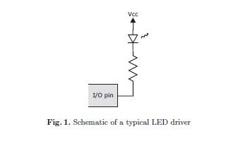
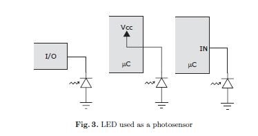
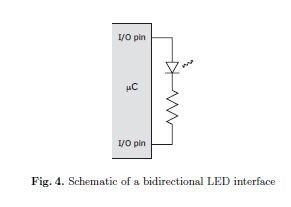
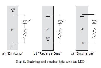
Using two digital i/o pins a microprocessor can be used to both emit and detect light through a LED. The concept is simple, switch the biasing of the diode for each condition depending on the circuit layout of the diode. Since the LED is a photodiode, sensitive to light that is above the spectrum at which it displays, it can be polled for the current light level it sees.


imageimage

Then you simulate the biasing of the LED in the microcontroller to emit and detect. Depending on the number of LEDs, even a low frequency uC could handle the job.
imageimage
The video attached to the post demonstrates how fast and accurate this interface can operate. Also attached is a document on building a touch LED interface, where the above Figure clips were taken from. My immediate idea is a fun interactive light wall for advertisement. But the versatility of this simple input has no bounds. Buttons for a device, a simple touch screen, a hand reconfigurable digital sign, to just name a few possibilities. But does it work in the dark?
 
See also "Engineer's Notebooks" 1977, By Forrest M. Mins. Mins describes how an LED can be used as a photodiode.
 
Cabe
Attachments:
TR2003-35.pdf

You don't have permission to edit metadata of this video.
Edit media
x
image
Upload Preview
image

  • Sign in to reply
  • Cancel
Parents
  • Former Member
    Former Member over 14 years ago

    The connection is straightforward, just connect the junction of the resistor and LED to an ADC pin on the processor.


    The circuit I attached here (UNTESTED!) connects this point to a pin that can also be configured as a comparator on a PIC12HV615-I/MFPIC12HV615-I/MF.

    (Note the HV version has a built in shunt regulator, and the data sheet explains how to set the supply resistor.  If you use a regulated 5V supply then use a PIC12F615.  The resistor in the programming connector allows ICD2 or ICD3 to supply the power at 5V to the HV chip)


    The comparator can be set so that it enables a counter/timer in the PIC (it can drive the T1G) so you can also measure the time that the diode takes to discharge for detecting presence of light.

    The pin can be reconfigured in software to be ADC input to measure the voltage when the LED is driven forwards and is illuminated.


    The sketch also shows how you might connect a microchip temperature sensor, which you could use to compare the results.  The temperature reading from the LED will be coarse as the ADC will change somewhere around 1.2degrees per bit, but this would be good enough say to control a room heater.


    The software would need to drive the LED forward for say, 200uS to emit a small amount of light to bounce of a finger if the LED is touched.

    During this time the ADC can be used to read the voltage on the LED.

    Then reverse the drive to the LED for say another 200uS and set the Timer1 so that it counts until the comparator flips. The count value indicates how much light is there.

    Then spend say 1600uS (so the total loop is 2mS) with the LED driven either off or on according to whether it should be visible or not.

    The short pulse of light will make the LED glow faintly, but this would be useful to find the switch in the dark...


    If I have some time I will write some code and try this...


    Note that the temperature sensor MCP9700DM-TH1MCP9700DM-TH1 will give approximately 0.5C resolution with the PIC on a 5V supply as shown.

    Finally, the circuit shown uses the internal voltage regulator so the ADC is not so accurate.  This isn't a circuit for precise, absolute temperature measurements.


    The attached Vishay data sheet has a graph of voltage against temperature. There are other manufactures and LEDs of course..this is just the first I found.


    (..and if the LED is connected to GP0 instead of GP1, it may be possible for the LED to be driven by a PWM signal with complementary outputs, to simplify the code)

    Attachments:
    imageLED Vishay page 6 temp curve tlcx510.pdf
    imageLED circuit.pdf
    • Cancel
    • Vote Up 0 Vote Down
    • Sign in to reply
    • Cancel
Reply
  • Former Member
    Former Member over 14 years ago

    The connection is straightforward, just connect the junction of the resistor and LED to an ADC pin on the processor.


    The circuit I attached here (UNTESTED!) connects this point to a pin that can also be configured as a comparator on a PIC12HV615-I/MFPIC12HV615-I/MF.

    (Note the HV version has a built in shunt regulator, and the data sheet explains how to set the supply resistor.  If you use a regulated 5V supply then use a PIC12F615.  The resistor in the programming connector allows ICD2 or ICD3 to supply the power at 5V to the HV chip)


    The comparator can be set so that it enables a counter/timer in the PIC (it can drive the T1G) so you can also measure the time that the diode takes to discharge for detecting presence of light.

    The pin can be reconfigured in software to be ADC input to measure the voltage when the LED is driven forwards and is illuminated.


    The sketch also shows how you might connect a microchip temperature sensor, which you could use to compare the results.  The temperature reading from the LED will be coarse as the ADC will change somewhere around 1.2degrees per bit, but this would be good enough say to control a room heater.


    The software would need to drive the LED forward for say, 200uS to emit a small amount of light to bounce of a finger if the LED is touched.

    During this time the ADC can be used to read the voltage on the LED.

    Then reverse the drive to the LED for say another 200uS and set the Timer1 so that it counts until the comparator flips. The count value indicates how much light is there.

    Then spend say 1600uS (so the total loop is 2mS) with the LED driven either off or on according to whether it should be visible or not.

    The short pulse of light will make the LED glow faintly, but this would be useful to find the switch in the dark...


    If I have some time I will write some code and try this...


    Note that the temperature sensor MCP9700DM-TH1MCP9700DM-TH1 will give approximately 0.5C resolution with the PIC on a 5V supply as shown.

    Finally, the circuit shown uses the internal voltage regulator so the ADC is not so accurate.  This isn't a circuit for precise, absolute temperature measurements.


    The attached Vishay data sheet has a graph of voltage against temperature. There are other manufactures and LEDs of course..this is just the first I found.


    (..and if the LED is connected to GP0 instead of GP1, it may be possible for the LED to be driven by a PWM signal with complementary outputs, to simplify the code)

    Attachments:
    imageLED Vishay page 6 temp curve tlcx510.pdf
    imageLED circuit.pdf
    • Cancel
    • Vote Up 0 Vote Down
    • Sign in to reply
    • Cancel
Children
No Data
element14 Community

element14 is the first online community specifically for engineers. Connect with your peers and get expert answers to your questions.

  • Members
  • Learn
  • Technologies
  • Challenges & Projects
  • Products
  • Store
  • About Us
  • Feedback & Support
  • FAQs
  • Terms of Use
  • Privacy Policy
  • Legal and Copyright Notices
  • Sitemap
  • Cookies

An Avnet Company © 2025 Premier Farnell Limited. All Rights Reserved.

Premier Farnell Ltd, registered in England and Wales (no 00876412), registered office: Farnell House, Forge Lane, Leeds LS12 2NE.

ICP 备案号 10220084.

Follow element14

  • X
  • Facebook
  • linkedin
  • YouTube