


(See here for part 1: Quick Review and Getting Started with the FRDM-KL46Z )
This post is to document some quick initial experiments with using the FRDM-KL46ZFRDM-KL46Z board from Freescale
After you’ve run the (very nice) demo, you’ll probably want to write your own code for it, to get to the classic blinking LED stage.
Is it difficult?
It contains an ARM processor so initial setup will be more tricky than small microcontrollers such as PIC/AVR where pretty much one sets up a data direction register (DDR) and then writes or reads a port register to control pins. Depending on the processor type you could be looking at configuring a peripheral identification address, a whole range of attributes (such as pull-up or deglitch modes) and initialising values. This instantly makes it look a lot more difficult to use ARM devices over smaller processors. Another point is that microcontrollers can contain more complex peripherals (such as ADCs and PWM) which may have tens of registers (each with 32 bits!) for configuration and it may take many hours to get up-to-speed with the details of it from the reference guides.
Can it be simplified?
Freescale offers a software product called Processor Expert that is supposed to help remove some of this pain by providing drag-and-drop ‘components’ which will auto-generate the appropriate set-up code.
The earlier post describes how to install CodeWarrior briefly and use it to compile an example application This current post records an attempt to use CodeWarrior with Processor Expert(called PE from now on below to start a new project Although this was done on a FRDM-KL46ZFRDM-KL46Z board the concept should be board and processor independent(as long as it is a Freescale processor type
Getting Started - New Project Wizard
Assuming you have already installed CodeWarrior and set up a workspace location (see the post referred to earlier for more information), you can run CodeWarrior and it should display a welcome screen (if you’ve already closed the welcome screen, you can re-open it using Help->Welcome). Click on the New Project Wizard.

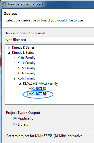
Select a project name (e.g. my-frdm-test). Then, navigate the ‘L’ series until you locate the correct microcontroller for the KL46Z board.
At the next step, deselect P&E and select OpenSDA:

Click Next until you see a ‘Rapid Application Development’ screen. Here you can enable PE:

You may see this message occasionally with Eclipse. Just wait for it to disappear.

Hardware Perspective
CodeWarrior should by now display a screen similar to this. This is called Hardware Perspective and there is also a C/C++ perspective which can be selected from the top-right.
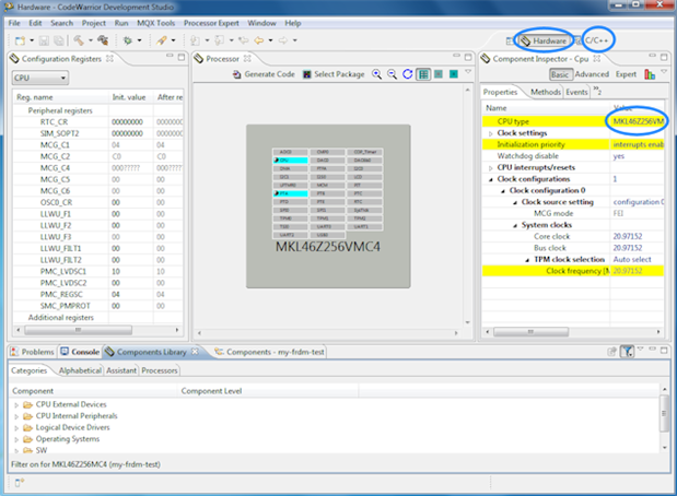
Within each perspective there is a lot of content (need a big screen!) with each pane known as a view. If you move things and accidentally end up with a messed-up perspective, you can restore the original by going to Window->Reset Perspective.
The processor in the center is a BGA version which doesn’t match the FRDM board, so click next to the CPU type as shown in the screenshot above and select the 100-pin LQFP version.
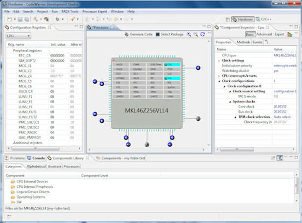
There is an asterisk next to the processor tab name, which means the file is now modified, so save it.

C/C++ Perspective
If you now go to the C/C++ perspective, you’ll see a screen like this:
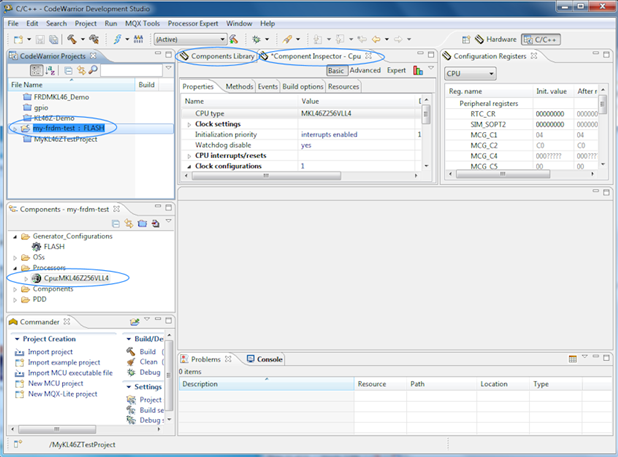
The important bits are marked. At the top left marking, you can see the open project name. This 'CodeWarrior Projects' titled pane (or View as mentioned earlier) is important because it contains the project names and files. It is possible to open or close any project visible here by right-clicking on it. When building a project (explained later), make sure that you have selected a project in this view first, before executing Project->Build Project. It is not something you need to do just yet.
In the screenshot above you can see that underneath the CodeWarrior Projects view/pane is a Components view which currently just contains the processor that was added. When selected, you’ll see the relevant attributes in the Component Inspector view. The Components Library view allows you to add additional items (such as an ADC). However, it is possible to do all this in the Hardware Perspective, so go back there for now.
Adding a Component
Back in the Hardware Perspective, the Components Library may have moved, to the bottom of the screen as shown in the screenshot below. If you can’t see it, go to Window->Show View->Components Library.

There are different ways of finding the feature that you want to add. In this example, go to Assistant and then scroll down to Digital input/output, double-click to see a Standard I/O folder and then double-click that to select Individual pins as shown here, and then right-click on it and select Add to Project.

Configuring the Component
Now that the feature has been added to the project, it can be configured using the Component Inspector which by default is at the top right:

The attributes like pin direction are listed, and the values can be modified by clicking on them. This is the basic view, but some hidden attributes may appear by clicking on Advanced or Expert. It is not needed in this case. There is also a graph-like icon that provides an alternate view that looks like this:

Clicking on the graph icon again reverts back to the original non-graph view. Use whichever one you feel comfortable with.
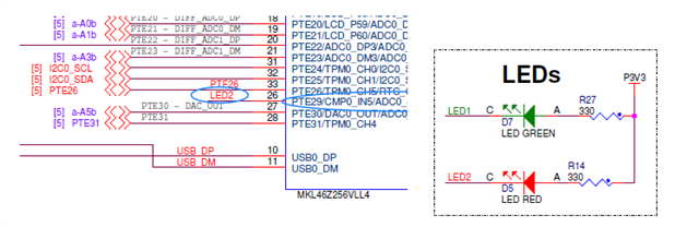
Looking at the FRDM-KL46ZFRDM-KL46Z schematic it can be seen that a red LED is wired here to a pin(pin 26 marked PTE29/CMP0IN5
Using this information it is possible to set the attributes until they look like this (I encountered a bug in the graphical view where it would display a red exclamation point even when there was no conflict, so I had to use the non-graph view).
Notice that in the diagram you can see a symbol showing Port E is now in use on that pin (pin 26). The Components view will also show the feature that was added. Since there is an asterisk on the Component Inspector view, save the change.

The initial value was set to zero, which means the LED will be lit (LED cathode is being controlled according to the circuit).
Using the Component in your Code
At this point, go back to the C/C++ Perspective and click Project->Build Project (don’t forget to select the project in the left side view first). Build Project will (amongst other things) perform these steps behind the scenes:
1. It will take the output from PE, auto-generate C files and compile them
2. It will compile your own code
3. It will link up all the individually-compiled files and make a single executable file that you can download to the board.
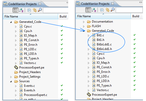
At this stage, although everything above will occur, we are only interested in using the Build Project for item 1 listed above, because we want to see the auto-generated files as a result of adding the 'Individual pins' I/O component earlier.
You’ll see in the Generated Code folder that some new files got created:
To use the feature, you’ll need to know what functions and events you can make use of. There are several ways to do this. One way is to right-click on the component and select Help on Component. There is lots of information including examples for many peripherals.

Another way is to click on Methods in the Component Inspector and you’ll see a list of them all, as shown here:

Or, you could double-click on the generated code files, and inspect the comments in the header file, or look at the C source file. Yet another way is to just hover over the names in the Components view, and some help will float on top.
The main() function actually has already been created, it is in a file under Sources called ProcessorExpert.c and if you open the file you can scroll down to it and find where it says ‘Write your code here’.

At that location, it is possible to drag the PutVal method directly into the C file.

The screenshot above shows what happens when you drag it across. The floating text occurred by hovering over the method in the Components view and it shows that a single parameter (bool Val) is required. The code was tidied up to look like this (a while loop to blink with a delay):
/* Write your code here */
/* For example: for(;;) { } */
int ledstate=0;
int i;
while(1)
{
Bit1_PutVal(ledstate);
ledstate=ledstate^1;
for (i=0; i<100000; i++);
}
/*** Don't write any code pass this line, or it will be deleted during code generation. ***/
Then, the code was saved and the project built again.
Creating an S-Record File
An S-record file (.srec) is needed for downloading into the board, but by default CodeWarrior doesn’t produce this, and only generates an ELF (.elf) file. There is an excellent site here that shows a way to create the .srec file this but sadly it didn’t work for me; it may work for you.
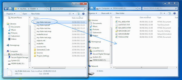
The workaround is to manually generate the file. To do this open a Windows Command prompt and navigate to your workspace and then to my-frdm-test/FLASH. You will see a file called my-frdm-test.elf was created during the build process. You can type this commands to convert to the S record format:
"C:\Freescale\CW MCU v10.4\Cross_Tools\arm-none-eabi-gcc-4_7_3\arm-none-eabi\bin\objcopy.exe" -O srec my-frdm-test.elf my-frdm-test.srec
Running the Code
You can now run it on the FRDM board by just plugging in the board and dragging the file to the USB drive:
The LED should now flash.
I also tried another peripheral that should have been straightforward (LCD peripheral) but it failed to work for me, and the reason is due to the fact that although many of the peripherals are simple to configure using PE, one that is difficult is the processor CPU itself, where there are many options for setting the clocks for example. I suspect my LCD wasn’t being clocked properly (it was extremely faintly turned on, so it had configured to some extent) or I had mis-programmed the voltage sources for the LCD. (EDIT: I figured out the LCD in the end - will write up the Processor Expert settings for it) It would be nice for Freescale to provide the PE settings for the processor CPU for the KL46Z board, so we don’t need to wade through dozens/hundreds of pages to deduce it.
Conclusions
Processor Expert does make things simpler; in this case, the 1000-page reference manual did not need to be consulted at all to make use of I/O. Clearly that will not be the case with more sophisticated peripherals where the reference manual will be needed but it always helps to have an expert system to double check your pin assignments and config register settings make sense for a peripheral.
It will greatly reduce the risk of bugs in register programming, and will help get programs running quicker.
Top Comments