


A Course in LabVIEW and Test Automation
Table of Contents
1 Briefing of labview and the challenge
Unlike other challenge, I have collaborated with NI FAEs in some projects and got to know Labview for some time. I am glad to be selected as challenger to code with Labview in GUI.
The labview is such a strong tool enough to build whole Automation factory PLC system in high standard. Since NI Labview is the first to bring about theconcept of Virtual machine, NI has invented this and widely applicable to high-end application such as aerospace, precise instrument, most of which is very expensive. There are wide range of sensors and actuators within the ecosystem fit for larger project. Industrial users can use lite version of host compater like NI Compact RIO for different applications.
This challenge is unique, since as far as I know this is the first of many kind can brings affordable sensor end with PICO SCPI Labtool.
2 The Plan and the outcome
The plan is to test motor operation and the performance, such as voltage, current, velocity, waveforms, etc, just like STM32cube Motor control GUI can do. In the end, I manage to catch some data, but not all. Since it would take much time on porting the Motor Control algorithm in Labview, the driver lib of BLDC is not so easy, I am not familiar with Labview enough to find some applicable Sub-VI to same time, even I know it does availalbe like SimpleFOC for arduino.
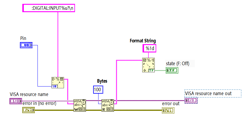
I manage to catch both Digital input data
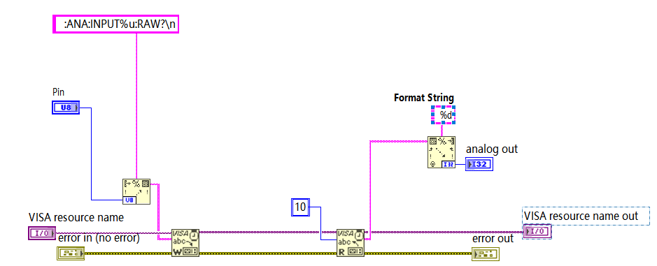
and Analogue input data with usbtmc_scpi_labtool,
Details in follows chapter.
3 Preparation
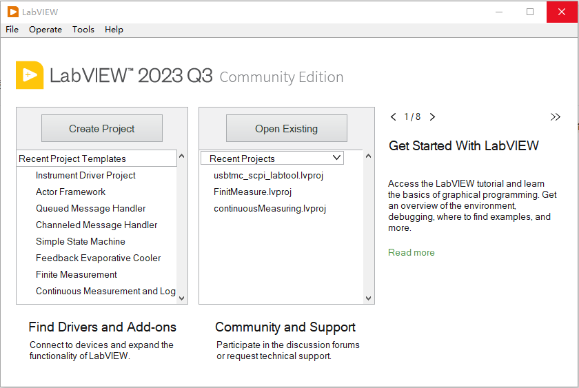
The fist this is to download and install Labview Community Version, it is easy once you have one NI account. There are cluster of programs to be installed if you like, but without licence they can not start. As I have mentioned before, this bundle is stong enough and worth the price. Mastering these tool with test-pass certification can be sought-after ability by clients. So start the labview
Then make one Raspberry Pi PICO ready with SCPI Labtool firmware flashed.
Then understand and familiar with PICO SCPI Labtool and how to use it.
Finally, the BLDC with digital reading Hall sensors,
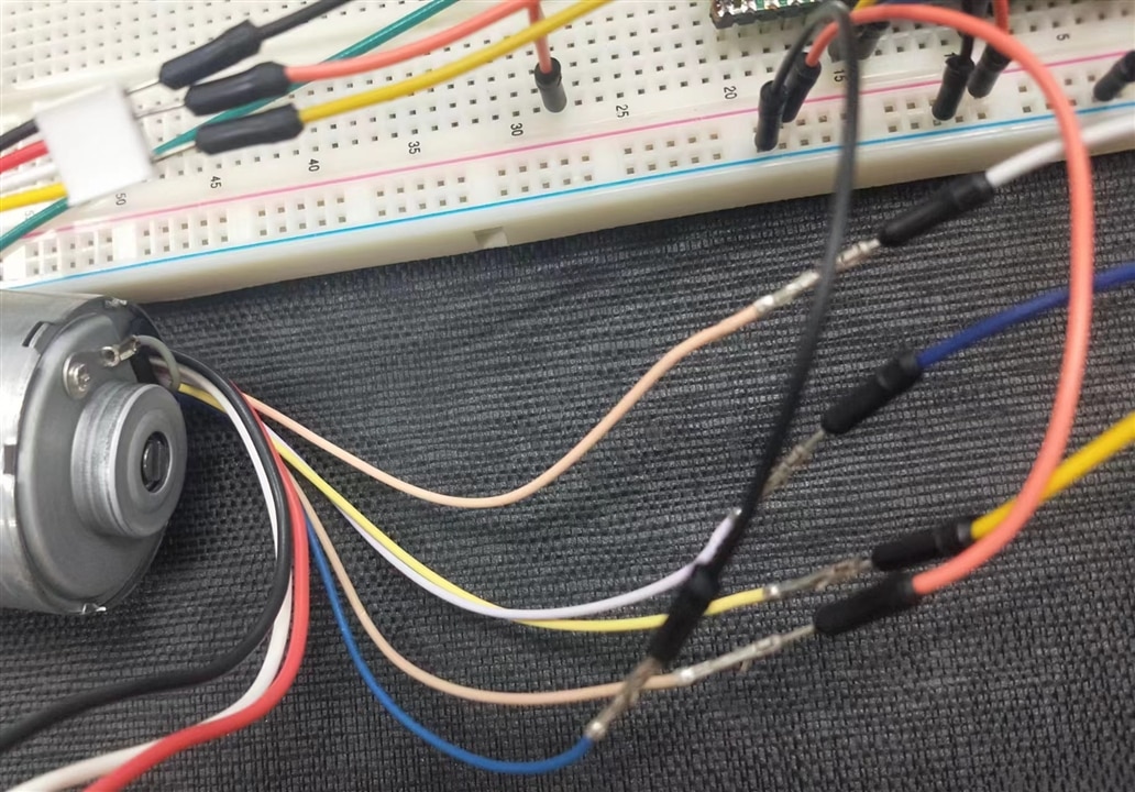
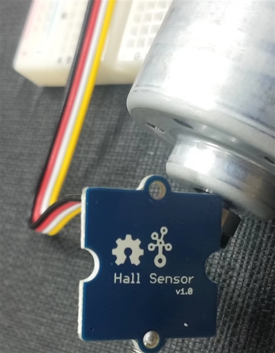
Analogue data reading Hall sensor expension board,
LED tester and motor driver board(available but not pass test at this moment), Raspberry Pi Pico expension board, DC power, multimeter, etc.
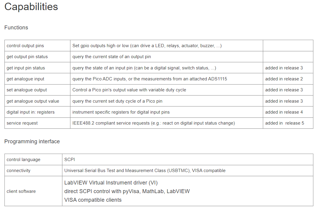
4 The Labview and SCPI Labtool
4.1 The Labview
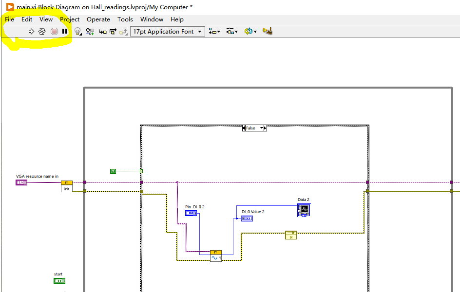
There have been reading document on how to use labview, but the best guide is to try and test. The knowledge matrix is complex, one have to go layers by layers to find the applet sub-VI to be used in coding. But the best part of labview is that it can be self guide and prompt errors with UI popup to find it. Start from correctly running code, noting the yellow part.
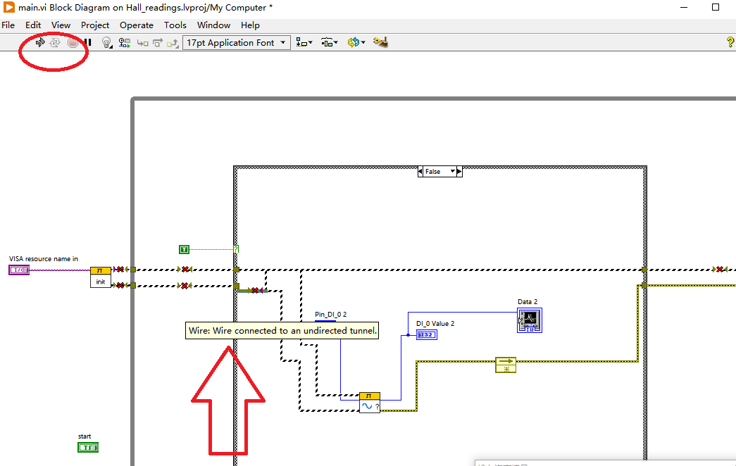
It add one wrong wire, noting the logo in read oval which report wrong instantly and prompt the reason in docking label once mouse move over the wrong wires.
4.2 SCPI Labtool
Thanks to hardwork of TOP members, the idea SCPI Labtool can be shorten to one bridge, one part runs on host compter, mimic one VISA port, can be access with NI VISA interactive control portal,
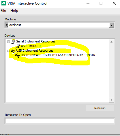
Double click the USB Instrument Resouces USB0:xxxxxxxxx, this is the Raspberry Pi PICO , parameters shall be
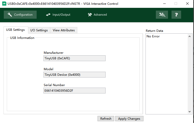
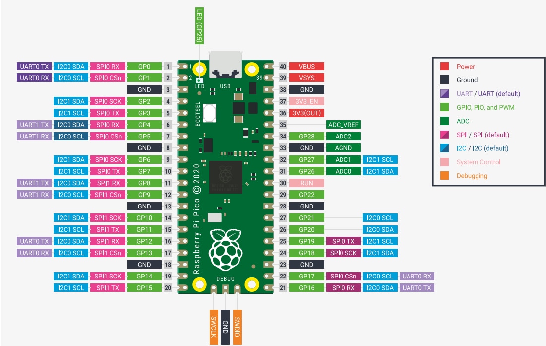
Do 1-2-3 as follows repeatly with different SCPI script, one can access Pins in Raspberry Pi PICO
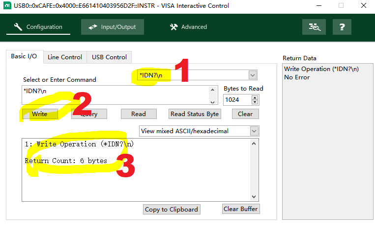
The other part is firmware of Raspberry Pi Pico, it is bridge, get the script from host computer like
*IDN?\n

Then parse the code, bridge the command to ports as read/write, digital/analogue,
Then binggo, the Raspberry Pi PICO is transparent, as if it does not there, the host computer control the ports.
That is it.
Another reason I can not complete original plan is that I can not allocate the ports properly, since this version of Labview_labtool support only 3x4=12 pins, there are more pins needed for motor testbench,such as Ua,Ub,Uc, Ia,Ib,Ic, Uresidue, Hall_A, Hall_B, Hall_C, Driver_AH, Driver_AL, Driver_BH, Driver_BL, Driver_CH, Driver_CL, etc. But as to this primary function test ,that is enough and perfect.
5 The Design and VI
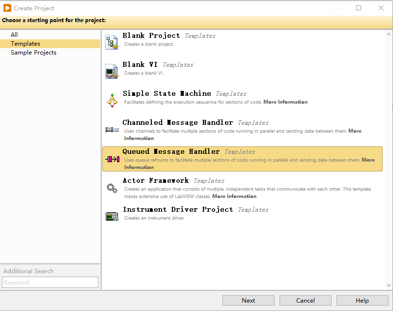
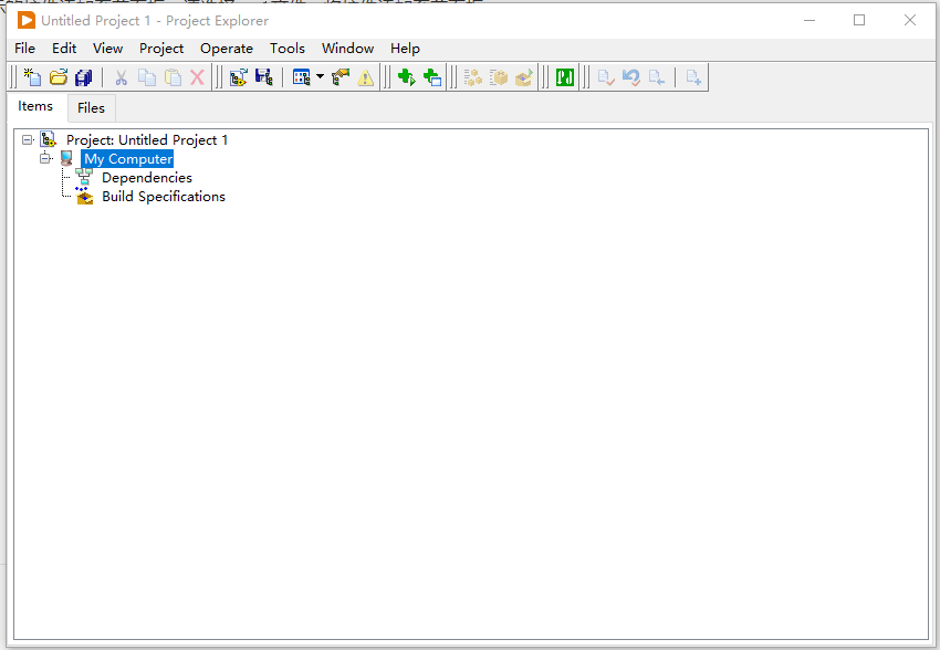
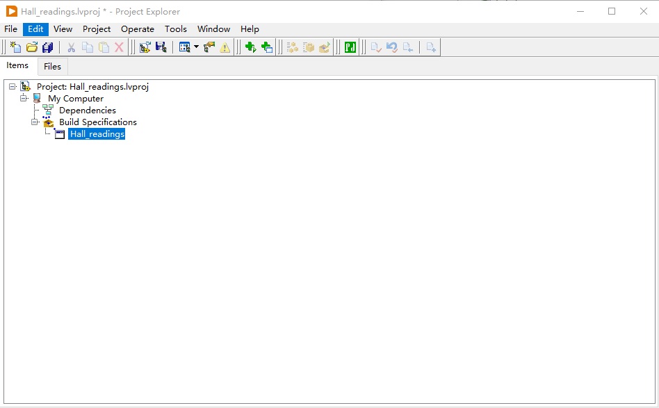
The design of Labview is creating and editing VI, create VI with blank project, of course, some sample project can be very useful as reference,
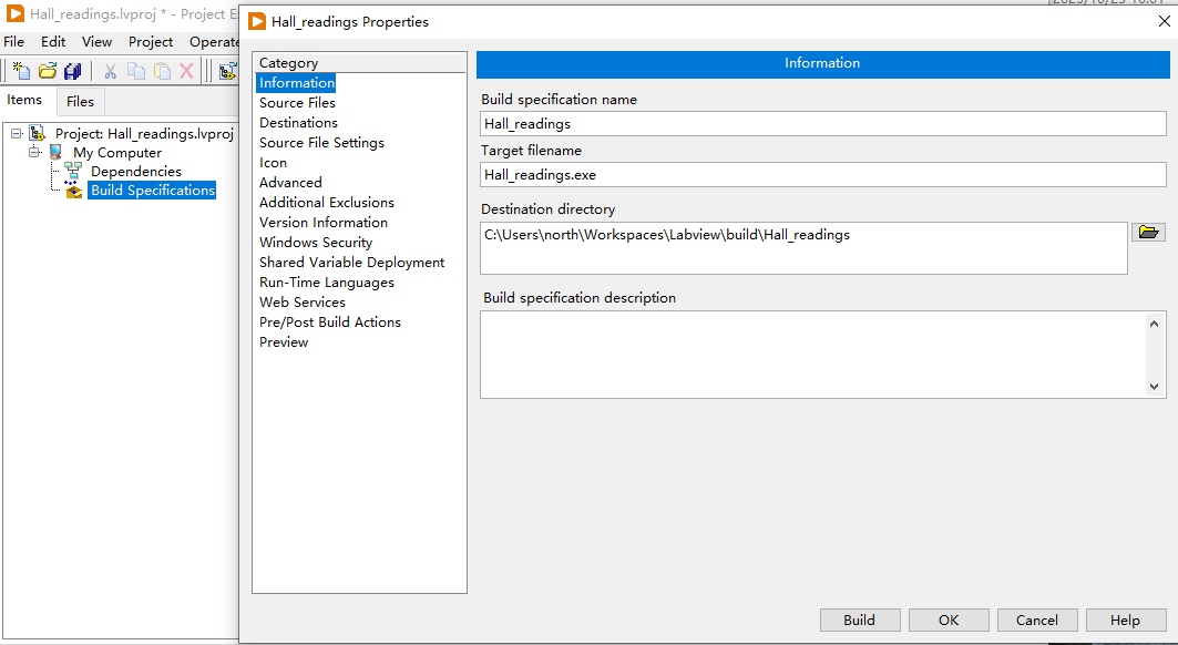
Press save and name the VI instead of Untitled, the VI can be compile to standalone runtime exe file if configuration build specifcation first,
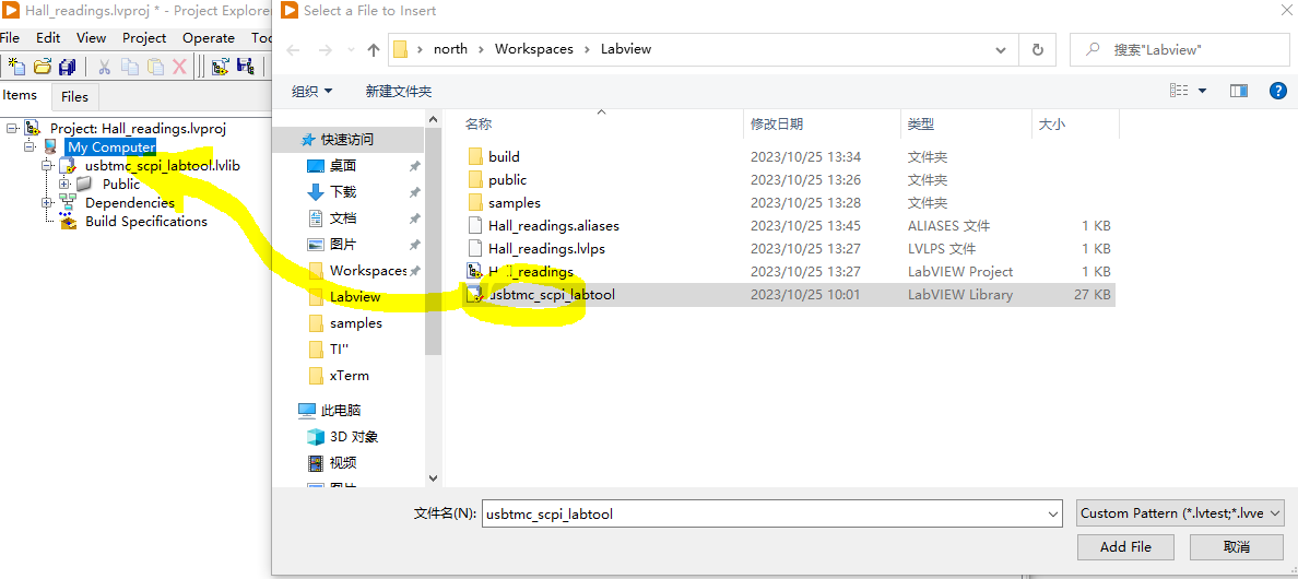
Add the SCPI labtool library first,
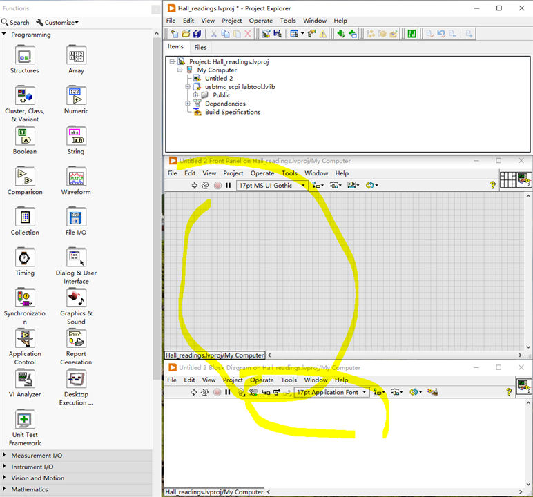
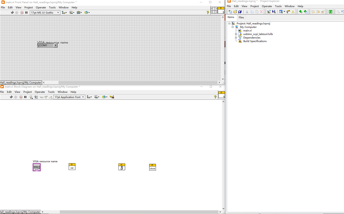
And create one VI as main.v as entrance VI, the function panel and front panel popup.
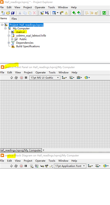
save to change name to main.v
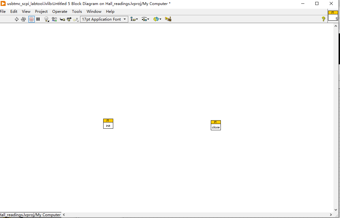
add functions and sub-VI one by one in front panel , for SCPI labtool, the Init and Close shall be put first with search VI
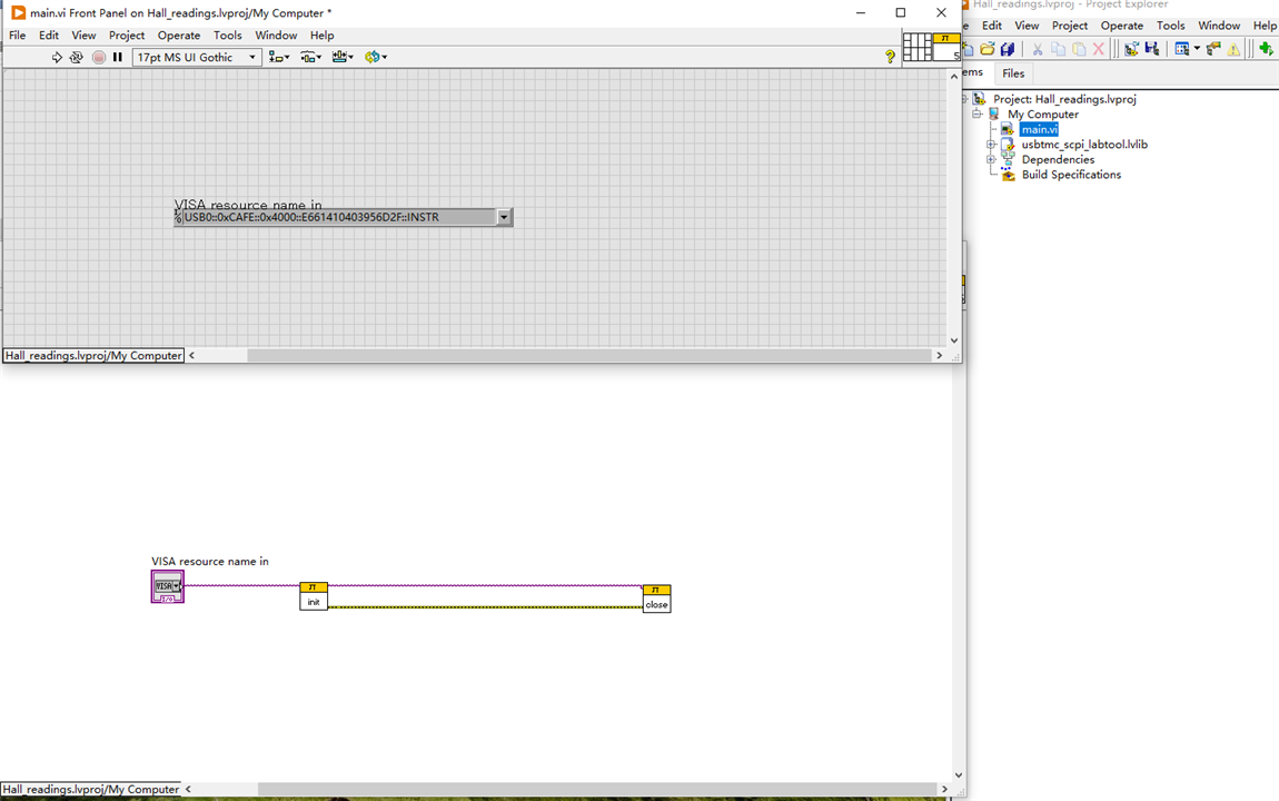
add VISA component In, this is where the USB0 resource come in,
Wire them accordingly, the following is basic program , doing nothing, but form the framework of this design.
Complete the fist design with reference to example digital read out,
6 The Result
Start the VI, control the digital output to control LED,

The LED is On - Off -On in sequence.

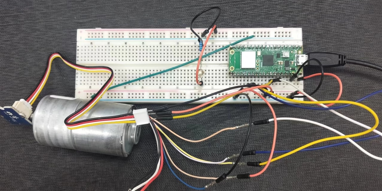
This is the raspberry Pi Pico on expension board, it works.
7 Step furher
As planned, add more pins from digital input from BLDC hall sensor and analogue input from Hall sensor board,

Revise the design
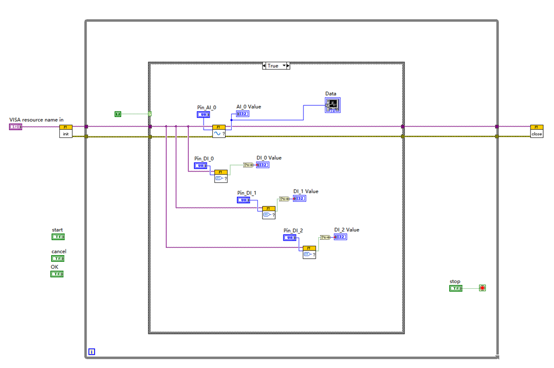
Start the VI, the front panel, show the three Hall sensor reading while the BLDC turns ,

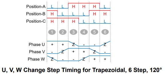
The sequence shall be as blow, marking the position of rotor,
Then the digital reading from BLDC Hall sensor in X-Y plotter
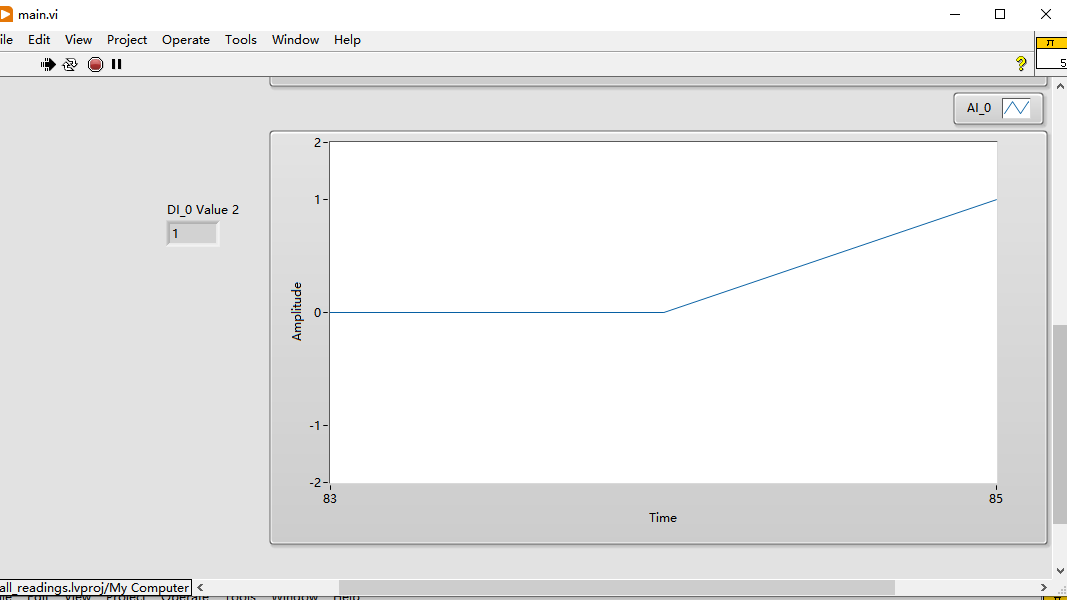
Then the analogu reading from Hall sensor in X-Y plotter
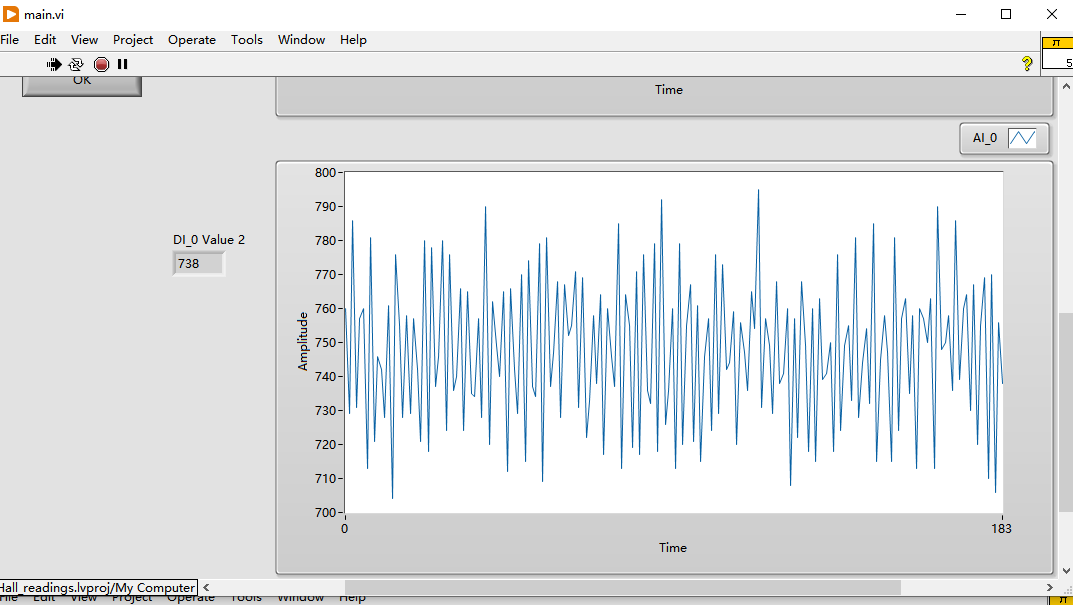
It works fine.
8 Conclusion
This final blog can brief outline how Raspberry Pi PICO run with SCPI labtool in NI labview environment, it is perfect. The reading of hall sensors mark the angle position of rotor, with the span time period, the running of motor in RPM can be calculated.
The high performance of Raspberry Pi Pico in ADC up to 1M/s can be enough for most voltage/current sample rate of 100-400kHz, the design of VI can be expended easily with more sensors added into this design.
Here is the source code in zip for reference.

