


Introduction:
As my final project, I am making a dc motor rpm monitor & control system using pi pico & labview. DC motor rpm will be temperature controlled. The motor rpm will keep decreasing as the temperature increases. If the temperature crosses a certain threshold, it will trip the circuit & the motor will stop.
Components Used:
- Pi Pico
- Labview
- 3v DC Motor
- Relay Module
- HC-89 Interrupt Sensor
- TIP122 NPN transistor
- KY-028 Digital Temperature Sensor (will be using analog pin)
SubVIs:
In this section, I will be going through the SubVIs that I used in my project.
Duty Cycle Control:
To be able to change the motor rpm, I am using a transistor as a switch which will turn on/off rapidly to control the supply voltage to the motor. For 3v supply, I am using the voltage pin of arduino. For switching, I am using the PWM in the pi pico. The VI is shown below:
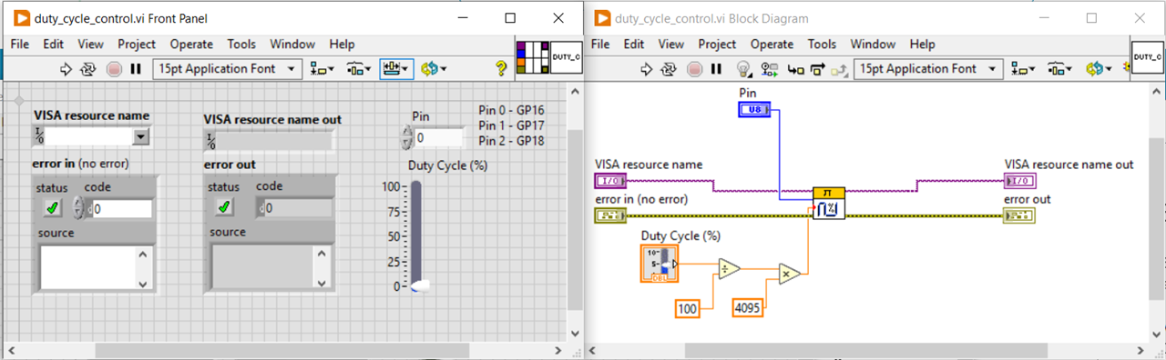
The duty cycle needs be passed in %. The subsequent logic will convert it to a real number in range (0, 4095). 4095 corresponds to highest duty cycle i.e. 100%.
I couldn't check & verify the pwm pulses generated as I don't have an oscilloscope  . But I checked the output dc voltage value on pin 0 (i.e. GP16) in a digital multimeter. At 50% duty cycle, it shows 1.64v & at 100% it shows 3.27v. So, I think it should work.
I connected a MOSFET (TIP122) between the motor and the supply. As can be seen in the video below, the motor doesn't start unless the duty cycle is >75% but once it starts, I can reduce the duty cycle to control its speed.
Getting temperature sensor data:
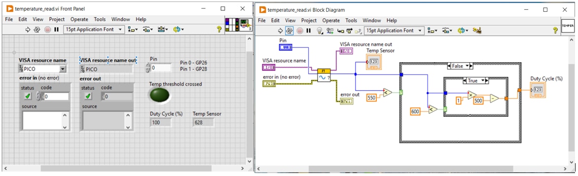
I have used a temperature sensor to keep monitoring the environmental temperature. The motor speed will keep changing based on the value read from this sensor. The higher the temperature, the lower will be the motor speed which will be controlled by varying the duty cycle.
By checking the analog reading from the sensor multiple times, I have identified the range between which the sensor data can vary. The range is (500, 600). 500 being hot and 600 being normal room temperature. If the sensor data reads value >600, 100% duty cycle will be applied. Below this value, the duty cycle will vary thus changing the motor speed. I am using 550 as the lower limit, if the sensor data reaches below that, the relay will disconnect the motor from the supply and the motor will stop. I am using an electric iron to increase the temperature.
Now, to be able to convert the sensor data to duty cycle value, I have created a simple linear relationship using the line equation: y=mx+c. The two endpoints of the line are (600, 100) & (550, 50).
m = (y2 - y1)/(x2 - x1) = (50 - 100)/(550-600) = 1
And c = 100 - 1*600 = -500
So, the line equation: y = x - 500
RPM Calculator:
I had written a blog earlier on calculating rpm. But that had some issues as suggested by community members. So, in this blog, I have taken their kind suggestions into account and tried my best to come up with an efficient rpm calculator.
I am using a photo interrupt sensor. It generates high data whenever an object comes in its front. I have a cpu cooler motor with 7 blades. So whenever a blade comes in front of the sensor, it will generate high data. Two consecutive high values mean 1/7 revolution has completed. Time difference between two consecutive high values can be used to calculate the rpm of the motor.
I have explained the rpm calculator part in the below sections:
Sensor Data Read:
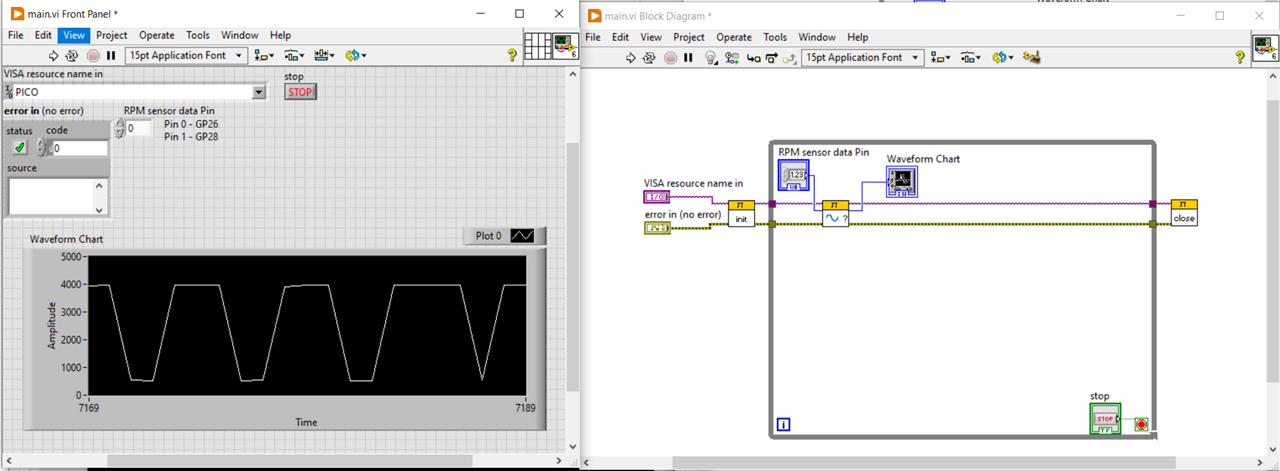
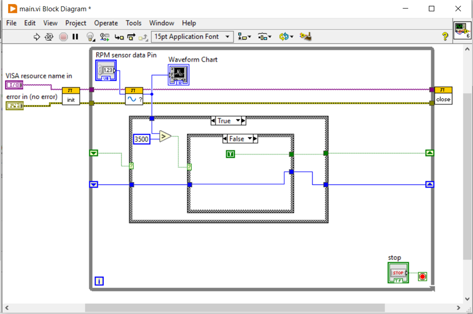
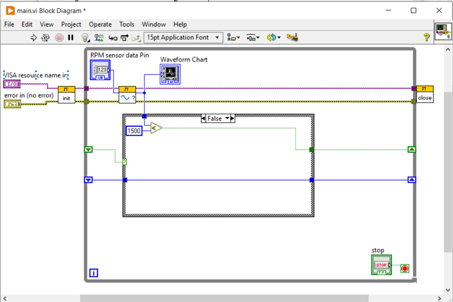
So, the below is the basic VI which read sensor data from pin 0 (i.e. GP26). I have put it in a while loop, so that it will continuously read the sensor data. I have also added a waveform chart temporarily to monitor the sensor data.
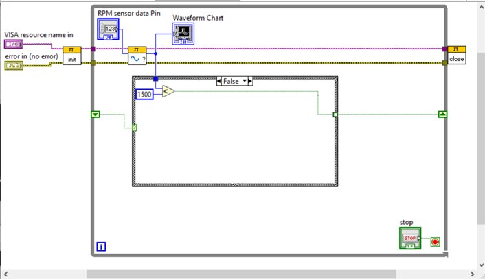
Detecting the positive edge of the sensor data:
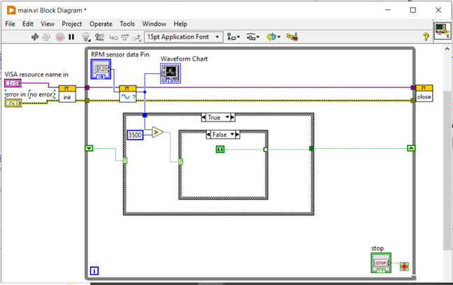
To detect when the blade passed through the sensor, it is very important to detect the positive edges of the data. I have used 1500 & 3500 as thresholds. If the sensor data is <1500, that means there is no object in front of the sensor, if it is >3500, that means there is an object passing through the sensor.
To implement the edge detection I have created an FSM using case structures & shift registers (to use values across loop iterations). I have pasted a code below for a case structure. The FSM works exactly like the below case statement will work if placed inside a while loop. Here SD means sensor data & shift means the value on the shift register.
case(shift)
	True:  (SD > 3500) ? (shift = False) : (shift = True);
	False: (SD < 1500) ? (shift = True) : (shift = False);
endcase
Calculating time between two consecutive blade passes:
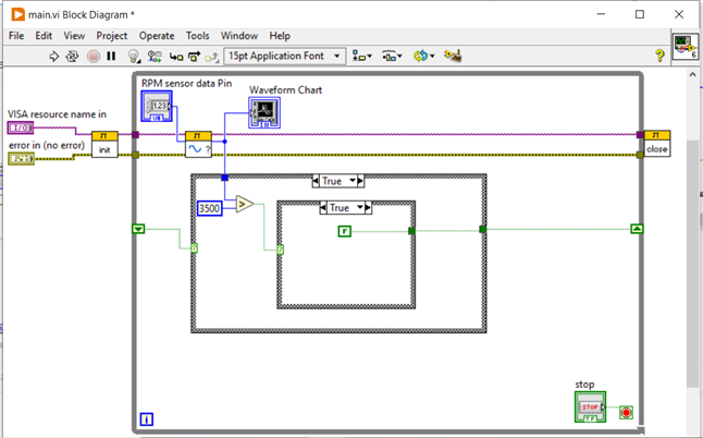
Now since we have detected the passing blade, we need to calculate the difference between the current timestamp & the previous timestamp. For this, I have used another shift register to store the previous timestamp & then subtract it from the current timestamp inside the inner case structure.
The timestamp should only get updated when a blade passes through the sensor (i.e. sensor data > 3500). In any other cases, it shouldn't get updated or we can say hold the previous value.
Calculating RPM:
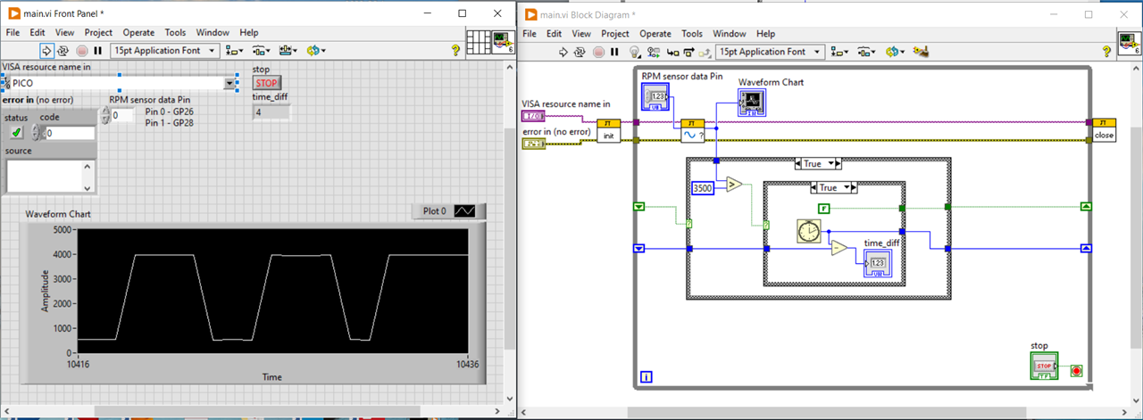
Now this time_diff (difference in timestamps in ms) can be used to calculate the rpm. My motor fan has 7 blades. So, this time_diff is for when one blade passes.
time_diff (for one revolution) = time_diff * 7
rpm = (1/time_diff)*60000
I have added one more shift register for storing time_diff and done direct connection with previous value for other cases to have some valid value even when the inner case structure is not running (i.e. case select is False).
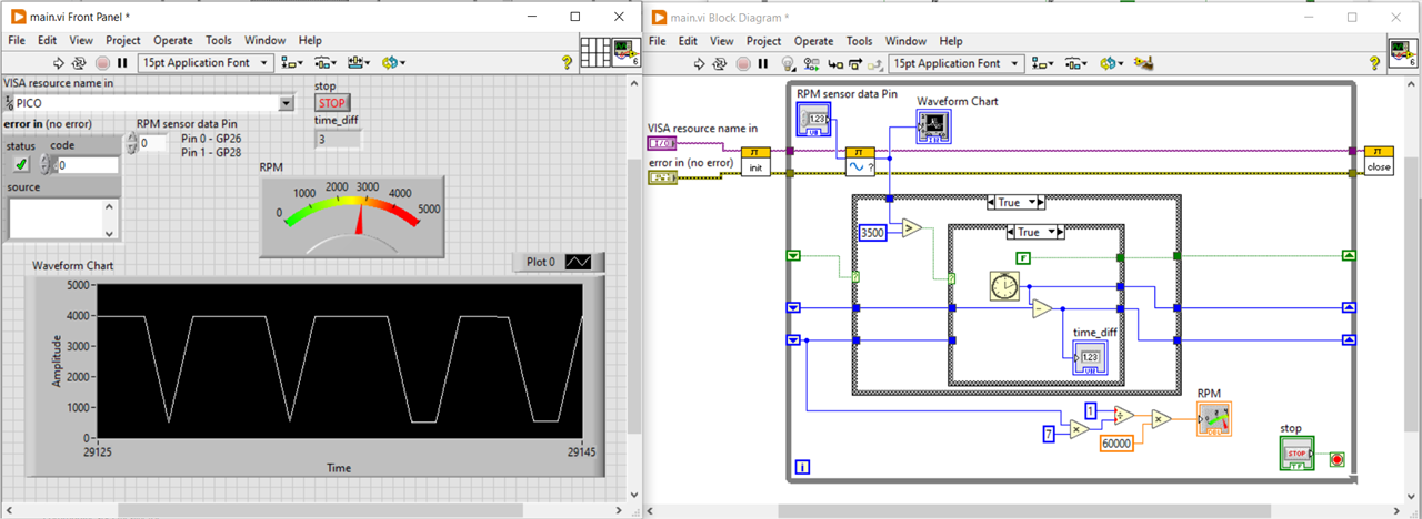
There is one problem in the above VI. The rpm meter is fluctuating very much between 2000 & 5000. Maybe that is because the time_diff value is also fluctuating between 3 &4. To avoid this I need to calculate the average rpm over some values.
Calculating average rpm:
To calculate average rpm, I have increased the number of elements in the shift register I created for storing the time_diff values. So, now I am storing the previous 10 time_diff values calculated and then taking their average and then calculating the rpm.
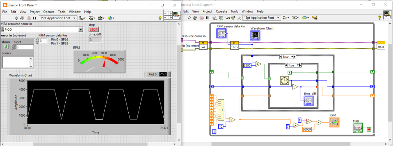
Its still fluctuating a little bit but its better than before. I think it will become more smooth if I add more elements but for now I will proceed with this.
The first video is without averaging & the next video is with averaging the rpm.
Till this point everything was working fine, but then suddenly my motor stopped working . I took another dc motor but I couldn't remove the fan from my previous motor. So, I had to create my own flywheel and cut a slot out of it. With new flywheel & only a single slot I had to do some minor adjustments in my VI. I replaced 1500 with 3000, '<' sign with '>', 3500 with 1000 & '>' sign with '<'. And now I have to multiply the time_diff by 1 instead of 7 since I have only single slot now. This motor is old and not performing that well but I don't have any other option right now.
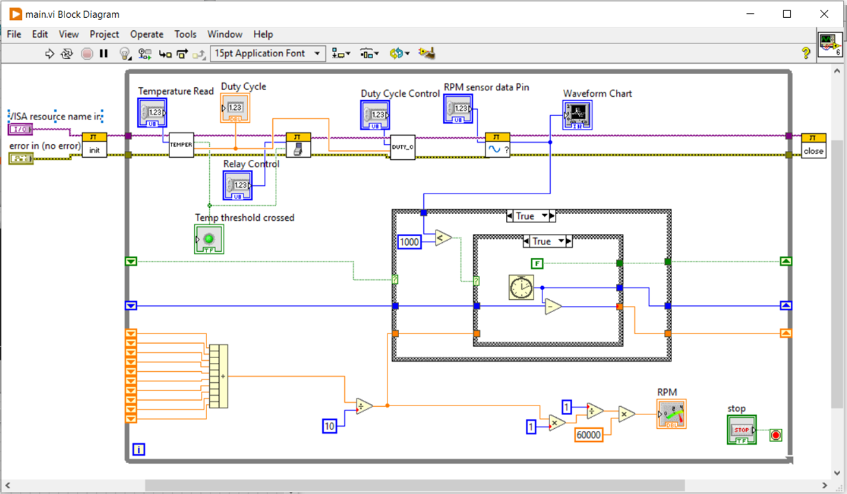
Adding duty cycle control VI:
Now, I added the duty cycle control VI to my main VI to change the speed of the motor. For now I have created a slider to control the duty cycle from 0 to 100 %. The motor stops below 50%. But we can vary the speed between 50% & 100%.
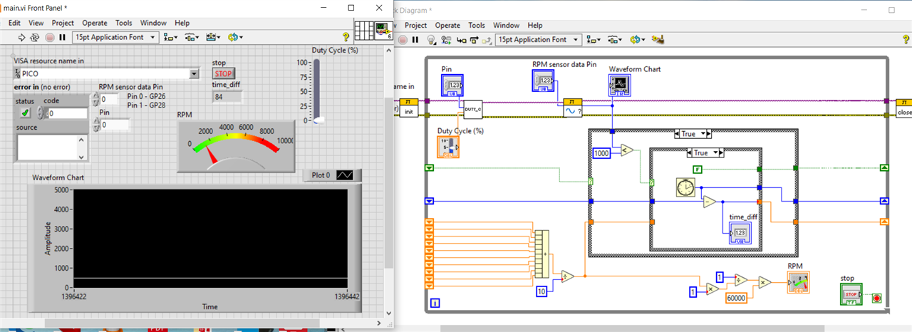
Adding temperature control to VI:
This is the last step. Since we can now control the motor speed using duty cycle, we are now going to control the duty cycle with temperature. To emulate high temperature, I am using an electric iron. As the temperature increases, the sensor data decreases. When it reaches below 550, the relay disconnects the supply and the motor stops.
Final Video:
The motor doesn't work properly, so I had to push it a little bit. I guess that is okay.
Circuit Diagram:
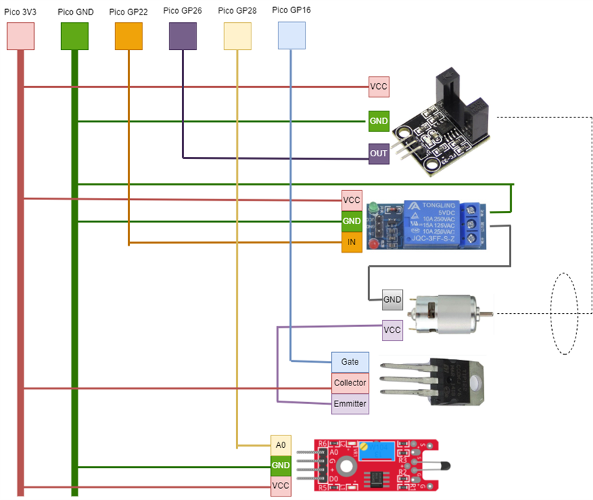
Conclusion:
Before starting the project, I thought it would be simple. But as I proceeded, it became clearer that there are many things that we need to keep in mind while using labview. Thanks to community members' suggestions, I was able to improve my VI but still there is some fluctuations in rpm calculated. There can be several reasons for this: old motor not working properly, fluctuations in current supplied from the arduino etc. But right now I don't any other option.
But even with these issues, I was able to see the rpm decreasing with temperature increase. So, I think the project is working.
I would also like to thank all the community members who helped in resolving issues that I faced and would like to welcome suggestions for any improvements in my project. This was a great experience working on this project and I am very positive that this experience will prove out to be very useful in future.
Github link for files.


