


Introduction:
In this blog, I will be creating a VI to calculate RPM. This VI will be a trial version. I will post a final blog later with the complete VI. I had already setup the pico board in my previous blog.
Components Used:
- Raspberry Pi Pico
- CPU Fan motor
- Photo Interrupt Sensor
- Relay Module
The plan was to use a BLDC motor with ESC so that I could control the motor speed by varying the duty cycle through pico. I first tested the motor on Arduino, it was working properly. But when I tried to implement the same on pico, it didn't work. So, I had to drop that idea and use a normal DC motor.
Circuit:
A rough circuit diagram is shown below:
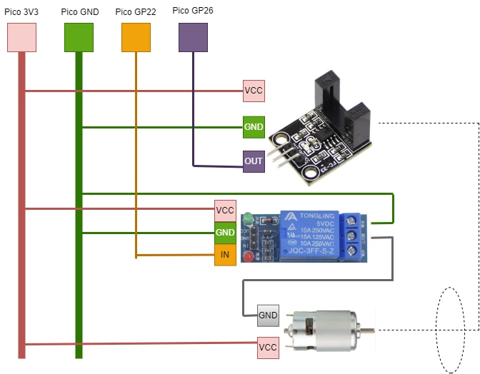
Working:
All the modules are supplied from the 3V3 source on pi pico. The relay controls the connection of the supply with the motor. The sensor and the relay by default has the supply. When the relay contacts are closed, the motor starts rotating. The motor has 7 blades on it. So, whenever a blade passes through the sensor, it generates data which is read by labview via the pico which is then used to calculate the RPM.
Labview VI:
In this section, I will be going through the subsections of the VI. I have uploaded the complete VI on github.
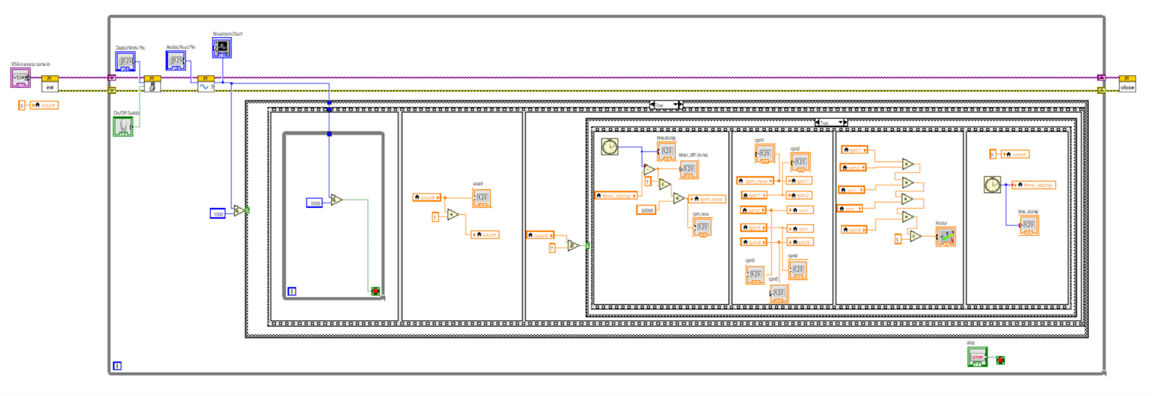
A snip of the complete VI is pasted below:
Block Diagram:
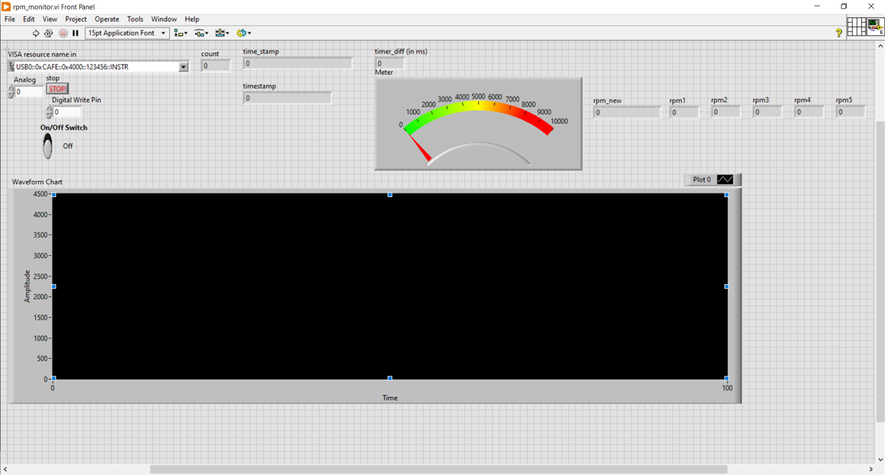
Front Panel:
1. Turning on the motor through relay (Digital Write):

The On/Off Switch can be used to turn on & off the motor through relay. The Digital Write Pin is set to 0 which corresponds to GP22 pin on pico for Digital Write. The GP22 is connected to the 'In' input of the relay module. When the switch is turned ON from the front panel, it sets the GP22 pin high and thus relay contact closes and motor turns on.
The motor fan has seven blades. A local variable 'count' is also initialized to keep count of how many blades has passed through the sensor. count = 7 means one revolution has completed. It will be used later
2. Reading from the photo interrupt sensor (Analog read):
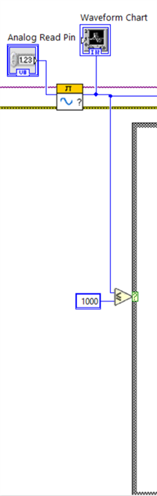
The analog read pin is set to 0 which corresponds to GP26 pin of the pico for analog read. A waveform chart is connected to the output to continuously monitor the data. The analog read data can vary between 0 & 4095. A case structure is added with condition that it should run only when there is no object in front of the sensor. The sensor will produce high data (around 4000) when there is an object in front of it.
3. Waiting for current blade to pass:
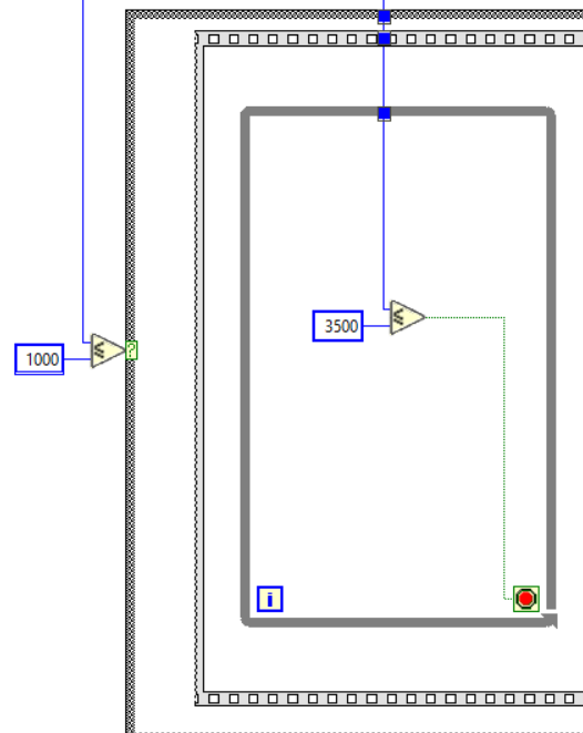
The sensor will output high value (around 4000) as long as a blade is in front of it. I have added a while loop after the sensor detects no object (i.e. sensor data <= 1000) which would wait for the sensor data to go high (i.e. wait for the next blade to come in front of it). Once the subsequent logic completes, it will again wait for lower sensor data. This way the logic will run only once per pulse (posedge of sensor data).
4. Counting number of blades passed:
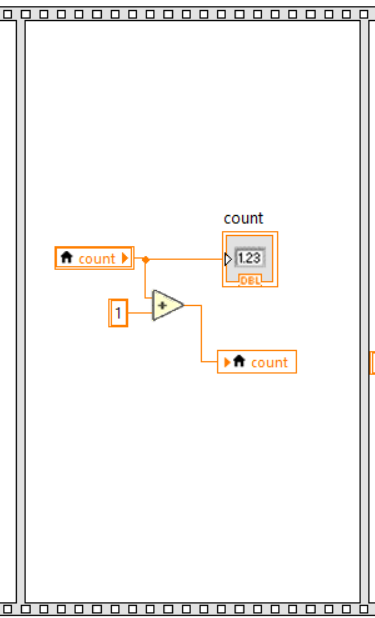
Once the positive edge of sensor data comes, it means, one blade has come in front of the sensor. When 7 posedge come, it means 7 blades have passed and one revolution is complete. In this section, it increments the 'count' variable that we declared earlier by 1 every time a blade passes.
5. One Revolution is complete:
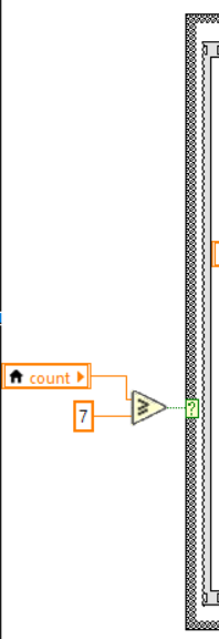
When one revolution is complete (i.e. count >= 7), the next section of logic executes.
6. Calculating the RPM:
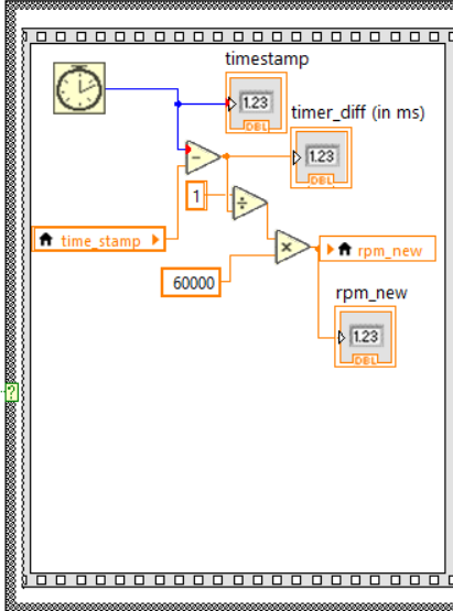
In this section, we calculate the time taken for one revolution and convert that into RPM. The time is calculated by taking difference between the current timestamp in ms and the timetstamp of the previous iteration (i.e. end of previous revolution) which was stored in a local variable 'time_stamp' in the previous iteration at a later section.
7. Taking Average of previous 5 RPMs:
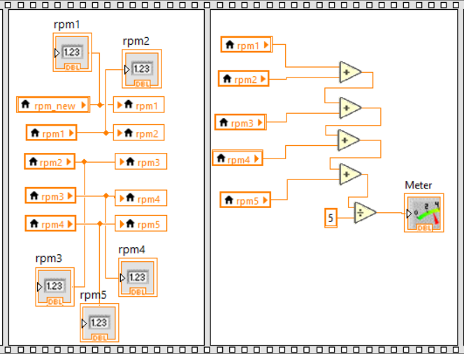
In this section, we first modify the previous array of RPMs adding the new RPM value calculated in the current iteration. And then calculate the average and show on a meter.
This section was specially included to avoid abrupt changes in RPM values.
8. Resetting the 'count' variable and setting 'time_stamp' for next iteration:
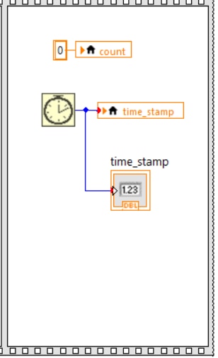
In this section, the 'count' variable is reset to 0 so that it can be used for the next iteration. And the 'time_stamp' variable is set.
Well, it seems the RPM calculated is not constant and changing continuously. The value seems to be between 2000 and 3000 rpm. I guess, I will have to do some modifications in the VI so that the rpm value doesn't change abruptly.
Summay:
This blog was expected to be the final project blog but it seems there are many improvements and changes that need to be done. So, I keep this blog as a rpm calculator trial and create another blog with improved VIs.
EDIT: Link to final project

