element14 Community
element14 Community
    Register Log In
  • Site
  • Search
  • Log In Register
  • About Us
  • Community Hub
    Community Hub
    • What's New on element14
    • Feedback and Support
    • Benefits of Membership
    • Personal Blogs
    • Members Area
    • Achievement Levels
  • Learn
    Learn
    • Ask an Expert
    • eBooks
    • element14 presents
    • Learning Center
    • Tech Spotlight
    • STEM Academy
    • Webinars, Training and Events
    • Learning Groups
  • Technologies
    Technologies
    • 3D Printing
    • FPGA
    • Industrial Automation
    • Internet of Things
    • Power & Energy
    • Sensors
    • Technology Groups
  • Challenges & Projects
    Challenges & Projects
    • Design Challenges
    • element14 presents Projects
    • Project14
    • Arduino Projects
    • Raspberry Pi Projects
    • Project Groups
  • Products
    Products
    • Arduino
    • Avnet Boards Community
    • Dev Tools
    • Manufacturers
    • Multicomp Pro
    • Product Groups
    • Raspberry Pi
    • RoadTests & Reviews
  • Store
    Store
    • Visit Your Store
    • Choose another store...
      • Europe
      •  Austria (German)
      •  Belgium (Dutch, French)
      •  Bulgaria (Bulgarian)
      •  Czech Republic (Czech)
      •  Denmark (Danish)
      •  Estonia (Estonian)
      •  Finland (Finnish)
      •  France (French)
      •  Germany (German)
      •  Hungary (Hungarian)
      •  Ireland
      •  Israel
      •  Italy (Italian)
      •  Latvia (Latvian)
      •  
      •  Lithuania (Lithuanian)
      •  Netherlands (Dutch)
      •  Norway (Norwegian)
      •  Poland (Polish)
      •  Portugal (Portuguese)
      •  Romania (Romanian)
      •  Russia (Russian)
      •  Slovakia (Slovak)
      •  Slovenia (Slovenian)
      •  Spain (Spanish)
      •  Sweden (Swedish)
      •  Switzerland(German, French)
      •  Turkey (Turkish)
      •  United Kingdom
      • Asia Pacific
      •  Australia
      •  China
      •  Hong Kong
      •  India
      •  Korea (Korean)
      •  Malaysia
      •  New Zealand
      •  Philippines
      •  Singapore
      •  Taiwan
      •  Thailand (Thai)
      • Americas
      •  Brazil (Portuguese)
      •  Canada
      •  Mexico (Spanish)
      •  United States
      Can't find the country/region you're looking for? Visit our export site or find a local distributor.
  • Translate
  • Profile
  • Settings
Cypress Kits
  • Products
  • Dev Tools
  • Cypress Kits
  • More
  • Cancel
Cypress Kits
Forum PSoC 4 Pioneer Kit Community Project#015 – CapSense Proximity Detection
  • Blog
  • Forum
  • Documents
  • Polls
  • Files
  • Members
  • Mentions
  • Sub-Groups
  • Tags
  • More
  • Cancel
  • New
Join Cypress Kits to participate - click to join for free!
Actions
  • Share
  • More
  • Cancel
Forum Thread Details
  • Replies 20 replies
  • Subscribers 31 subscribers
  • Views 3569 views
  • Users 0 members are here
  • 100projects
Related

PSoC 4 Pioneer Kit Community Project#015 – CapSense Proximity Detection

cy.wbz
cy.wbz over 12 years ago

Hello!


This example demonstrates to users how to create a CapSense proximity sensor. This example will use the proximity sensor value to mix a color on an RGB LED. The user will also be able to read the data out using the UART and Bridge Control Panel.


image


Forum Post Attachments:


At the bottom of this post we are including the following items:

  • Example Project Zip File
  • Zip File of Images
    • Project Schematic
    • Component Configurations


Components Used:


The user can download the example project at the bottom of this post. The project uses the following list of Creator Components:

  • CapSense
  • UART
  • PWM
  • CyClock
  • CyPin


The components are configured by right clicking on the component in your Top Design schematic view and selecting Configure. Please enable the following selections in the Configuration windows for the listed components above.


Firmware Description:


The main.c firmware is included in the example project. Please review the commented sections for more details.


The example project firmware implements a proximity sensor, which is available in the CapSense component under the configuration GUI.


The example project endlessly reads the proximity values from the sensor and calibrates a proximity maximum range. This value is used to calculate the LED color using the LED RGB driver module.You will remember that we used this LED Driver module in example #014.


The hue for the LED is calculated using the proximity value and then passed to the APIs defined in the LED RGB driver file. The value of the hue is then also passed to the UART as two 8 bit values to be displayed in the Bridge Control Panel.


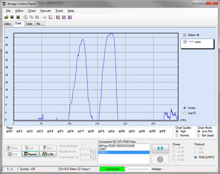
To monitory the values from the UART the user will need to launch the Bridge Control Panel and select the COM port from the port list. This will automatically select the RX8 (UART) radio button. In my example the COM port is COM13. Enter in the following UART command into the Bridge Control Panel and then hit the repeat button.


RX8 [h=43] @1prox @0prox


You will see the UART data displayed in the output window. Navigate to the Chart tab to see the proximity values displayed in the chart window. Move your hand around the proximity wire and see the values change in the chart. In the below image you see a plot of the values from the UART. The peaks are when my hand is close to the proximity sensor.


image


A key point when using the Bridge Control Panel. The PWM value is a 16 bit value in your application but it is broken into two 8 bit values when transmitted. Here the Bridge Control Panel reads those values and reassembles the two 8 bit values into a single 16 bit value. It accomplishes this by using the '0' and '1' leading values on the read variables.


RX8 [h=43] @1prox @0prox


In the above command we have a variable named 'prox'. We add a leading 1 and 0 to the variable to indicate that these two values should be stitched together to create a single value and assign that value to 'prox'. If the '0' and '1' values are placed after 'prox', for example prox1 or prox0 then this indicates two separate variables. For more information on this please take a look at the Bridge Control Panel user guide.


Hardware Connections:


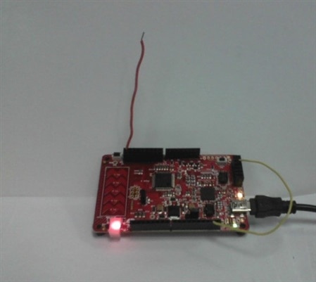
The user will need to connect a single wire to the P1[0] pin on the Pioneer Kit. The P1[0] is on the J2 header. This wire should be long and be pointed vertically away from the board. This help to reduce noise on the proximity detection.


Also connect a single wire to the PSoC 4 pin P4[1] and the Pin 9 on the header J11. This will connect the UART of the PSoC 4 to the UART Bridge on the PSoC 5LP. This wire will enable the Bridge Control Panel UART data collection. In this example we only need the TX connection from the PSoC 4 as we are not sending values to the PSoC 4.


Test Your Project:


Once the kit is programmed wait until the LED transitions from White to Red. The proximity detector is finding the minimum and maximum values. Once it transitions to Red move your hand close to the wire and see that the LED changes color as you get closer to the wire. Use the Bridge Control Panel to read the proximity value.


I hope this example can help you out in your design.


Best,

Matt

Attachments:
KIT042_Proximity.cydsn.zip
3817.Project Images.zip
  • Sign in to reply
  • Cancel

Top Replies

  • DAB
    DAB over 12 years ago +1
    A very good way to teach people about the capacitive touch technology. They get a "feel" for the sensor sensitivity and they could experiment with using different types of gloves that could be used with…
  • jesusantoniocar
    jesusantoniocar over 12 years ago in reply to DAB +1
    Hello Matt. escellent example, i can learn about of capacity sensors, and DAB have reason , it will be a very interesting project to the comprehensive study to look at the changes in capacitance over time…
  • jesusantoniocar
    jesusantoniocar over 12 years ago in reply to jesusantoniocar +1
    Hello Matt. Thanks, i found the application , initially I tested the program using hyerterminal, but i test the application with Bridge Control Panel and runs great, best regards, jesus antonio
Parents
  • johndumais
    johndumais over 9 years ago

    Thanks for sharing this tutorial with us. It is helpful in building the capsense proximity sensor and for detection also.

    I want to know which capsense you are using? What is the duty cycle of PWM you are using here? Have you tested it and if tested what problems you got?


    printed circuit assembly

    • Cancel
    • Vote Up 0 Vote Down
    • Sign in to reply
    • Cancel
Reply
  • johndumais
    johndumais over 9 years ago

    Thanks for sharing this tutorial with us. It is helpful in building the capsense proximity sensor and for detection also.

    I want to know which capsense you are using? What is the duty cycle of PWM you are using here? Have you tested it and if tested what problems you got?


    printed circuit assembly

    • Cancel
    • Vote Up 0 Vote Down
    • Sign in to reply
    • Cancel
Children
No Data
element14 Community

element14 is the first online community specifically for engineers. Connect with your peers and get expert answers to your questions.

  • Members
  • Learn
  • Technologies
  • Challenges & Projects
  • Products
  • Store
  • About Us
  • Feedback & Support
  • FAQs
  • Terms of Use
  • Privacy Policy
  • Legal and Copyright Notices
  • Sitemap
  • Cookies

An Avnet Company © 2025 Premier Farnell Limited. All Rights Reserved.

Premier Farnell Ltd, registered in England and Wales (no 00876412), registered office: Farnell House, Forge Lane, Leeds LS12 2NE.

ICP 备案号 10220084.

Follow element14

  • X
  • Facebook
  • linkedin
  • YouTube