element14 Community
element14 Community
    Register Log In
  • Site
  • Search
  • Log In Register
  • About Us
  • Community Hub
    Community Hub
    • What's New on element14
    • Feedback and Support
    • Benefits of Membership
    • Personal Blogs
    • Members Area
    • Achievement Levels
  • Learn
    Learn
    • Ask an Expert
    • eBooks
    • element14 presents
    • Learning Center
    • Tech Spotlight
    • STEM Academy
    • Webinars, Training and Events
    • Learning Groups
  • Technologies
    Technologies
    • 3D Printing
    • FPGA
    • Industrial Automation
    • Internet of Things
    • Power & Energy
    • Sensors
    • Technology Groups
  • Challenges & Projects
    Challenges & Projects
    • Design Challenges
    • element14 presents Projects
    • Project14
    • Arduino Projects
    • Raspberry Pi Projects
    • Project Groups
  • Products
    Products
    • Arduino
    • Avnet Boards Community
    • Dev Tools
    • Manufacturers
    • Multicomp Pro
    • Product Groups
    • Raspberry Pi
    • RoadTests & Reviews
  • Store
    Store
    • Visit Your Store
    • Choose another store...
      • Europe
      •  Austria (German)
      •  Belgium (Dutch, French)
      •  Bulgaria (Bulgarian)
      •  Czech Republic (Czech)
      •  Denmark (Danish)
      •  Estonia (Estonian)
      •  Finland (Finnish)
      •  France (French)
      •  Germany (German)
      •  Hungary (Hungarian)
      •  Ireland
      •  Israel
      •  Italy (Italian)
      •  Latvia (Latvian)
      •  
      •  Lithuania (Lithuanian)
      •  Netherlands (Dutch)
      •  Norway (Norwegian)
      •  Poland (Polish)
      •  Portugal (Portuguese)
      •  Romania (Romanian)
      •  Russia (Russian)
      •  Slovakia (Slovak)
      •  Slovenia (Slovenian)
      •  Spain (Spanish)
      •  Sweden (Swedish)
      •  Switzerland(German, French)
      •  Turkey (Turkish)
      •  United Kingdom
      • Asia Pacific
      •  Australia
      •  China
      •  Hong Kong
      •  India
      •  Korea (Korean)
      •  Malaysia
      •  New Zealand
      •  Philippines
      •  Singapore
      •  Taiwan
      •  Thailand (Thai)
      • Americas
      •  Brazil (Portuguese)
      •  Canada
      •  Mexico (Spanish)
      •  United States
      Can't find the country/region you're looking for? Visit our export site or find a local distributor.
  • Translate
  • Profile
  • Settings
Cypress Kits
  • Products
  • Dev Tools
  • Cypress Kits
  • More
  • Cancel
Cypress Kits
Forum PSoC 4 Pioneer Kit Community Project#039 - Two PWMs for the price of one
  • Blog
  • Forum
  • Documents
  • Polls
  • Files
  • Members
  • Mentions
  • Sub-Groups
  • Tags
  • More
  • Cancel
  • New
Join Cypress Kits to participate - click to join for free!
Actions
  • Share
  • More
  • Cancel
Forum Thread Details
  • Replies 4 replies
  • Subscribers 28 subscribers
  • Views 2375 views
  • Users 0 members are here
  • 100projects
Related

PSoC 4 Pioneer Kit Community Project#039 - Two PWMs for the price of one

cy.wbz
cy.wbz over 12 years ago

Hello!


In this example we are going to create dual PWM outputs from a single TCPWM component. While this example may not be as flashy as some of the previous examples it is showcasing the power of PSoC and the configurability of the peripheral resources. In this example we are looking at a design challenge that an engineer may face. You have already consumed your TCPWM and UDB resources, but you need another PWM to control a motor or LED. In this example we are going to show you two examples on how to accomplish this task, first will be in firmware, the second will be accomplished in hardware.


Forum Post Attachments:


At the bottom of this post we are including the following items:

  • Example Project Zip File
  • Zip File of Images
    • Project Schematic
    • Component Configurations


Components Used:


The user can download the example project at the bottom of this post. The project uses the following list of Creator Components:

  • TCPWM
  • Mux
  • Toggle Flip Flop
  • CyClock
  • CyPin
  • Control Register


The components are configured by right clicking on the component in your Top Design schematic view and selecting Configure. Please enable the following selections in the Configuration windows for the listed components above.


Firmware Description:


The main.c firmware is included in the example project. Please review the commented sections for more details.


In the attached workspace contains two projects “Dual_TCPWM” and “Dual_with_macrocells”. Both of these examples address the challenge of creating two PWM outputs from a single PWM.


image


Dead Time-Based


The first, purely firmware-based method relies on using dead time together with the TCPWM’s compare value and clever manipulation of the PWM’s output inversion to effectively decouple the TCPWM’s two outputs.  Due to the reliance on dead time, this method is limited to periods of up to 255, as dead time is also limited to 255 counts.


image


The positive PWM output follows the below equation:


image


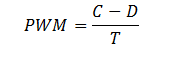
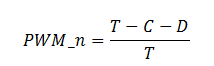
Where C is TCPWM compare, D is dead time, and T is PWM period.  The negative PWM output (PWM_n) follows the below equation:


image


Using these two equations, we can set up a system of equations that allows us to solve for the compare value and dead time for any configuration of PWM and PWM_n:


image


Reducing this matrix gives us the following for compare and dead time:


image


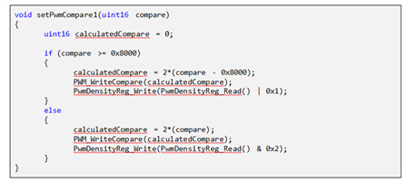
Unfortunately, though, this yields negative results for dead time when the two PWM densities sum to more than 1.  To solve this problem, both outputs are negated, and the two input densities are switched before compare and dead time are calculated.  The code below demonstrates how this technique would be used to configure a TCPWM PWM:


image


PLD-Based


The PLD-based method relies on external logic and compare-swapping inside the TCPWM.  This method allows 16-bit resolution, but uses 5 p-terms, 3 macrocells, and 2 control register bits.


image


This method uses the TCPWM’s OV output to trigger its own switch input, switching between its two compare registers.  In this way, the output of the TCPWM is only driving one of the outputs at a given time, while the other is being driven by a control register.


image


The control register is written with a 0 or 1 depending on the amplitude of the desired compare.  The T flip flop automatically switches the mux so that the outputs are kept in sync. The code for configuring this TCPWM follows:


image


Hardware Connections:


There are no hardware connections for this example. We are showcasing how to create dual PWM outputs from a single PWM component. The user could connect to an o-scope to watch the output.


Test Your Project:


Program your example and connect the output pins to an o-scope to view the dual PWM ouputs.


I hope this example can help you in your design.


Best,

Matt


Attachments:
dual_tcpwm.cywrk.Archive01.zip
5165.Project Images.zip
  • Sign in to reply
  • Cancel

Top Replies

  • jesusantoniocar
    jesusantoniocar over 12 years ago +1
    Hello Matt, Gagan. Another great project. thanks. jesus players.brightcove.net/.../index.html
  • DAB
    DAB over 12 years ago +1
    I like it. Sometimes you just need another pulse source to run some timing. Using the same PWM device keeps the synchronization but enables two slightly different pulse for counters or delay lines. I think…
  • jesusantoniocar
    jesusantoniocar over 12 years ago

    Hello Matt, Gagan.

    Another great project.


    thanks.


    jesus

    You don't have permission to edit metadata of this video.
    Edit media
    x
    image
    Upload Preview
    image

    • Cancel
    • Vote Up +1 Vote Down
    • Sign in to reply
    • Cancel
  • DAB
    DAB over 12 years ago

    I like it.


    Sometimes you just need another pulse source to run some timing.  Using the same PWM device keeps the synchronization but enables two slightly different pulse for counters or delay lines.


    I think I am starting to get the hang of your hardware.  Very cool stuff.


    DAB

    • Cancel
    • Vote Up +1 Vote Down
    • Sign in to reply
    • Cancel
  • cy.gul
    cy.gul over 12 years ago in reply to DAB

    precisely! the digital fabric of PSoC allows the user to create custom logic around the single 16-bit PWM, to get a second synchronous output that has its own 16-bit Compare value.

    • Cancel
    • Vote Up 0 Vote Down
    • Sign in to reply
    • Cancel
  • Former Member
    Former Member over 10 years ago

    Hi all,

    @Matthew Amazing work

    I also have to do the same Task for my Project. But bit different.

    Project is in PSoC 5LP.I have 2 Analog Input for Setting PWM Freq & deadtime.


    pls check my attached Project.


    Regards

    Shveta

    Attachments:
    Final_Project.cywrk.Archive01.zip
    • Cancel
    • Vote Up 0 Vote Down
    • Sign in to reply
    • Cancel
element14 Community

element14 is the first online community specifically for engineers. Connect with your peers and get expert answers to your questions.

  • Members
  • Learn
  • Technologies
  • Challenges & Projects
  • Products
  • Store
  • About Us
  • Feedback & Support
  • FAQs
  • Terms of Use
  • Privacy Policy
  • Legal and Copyright Notices
  • Sitemap
  • Cookies

An Avnet Company © 2025 Premier Farnell Limited. All Rights Reserved.

Premier Farnell Ltd, registered in England and Wales (no 00876412), registered office: Farnell House, Forge Lane, Leeds LS12 2NE.

ICP 备案号 10220084.

Follow element14

  • X
  • Facebook
  • linkedin
  • YouTube