Hello!
In this example we are going to create dual PWM outputs from a single TCPWM component. While this example may not be as flashy as some of the previous examples it is showcasing the power of PSoC and the configurability of the peripheral resources. In this example we are looking at a design challenge that an engineer may face. You have already consumed your TCPWM and UDB resources, but you need another PWM to control a motor or LED. In this example we are going to show you two examples on how to accomplish this task, first will be in firmware, the second will be accomplished in hardware.
Forum Post Attachments:
At the bottom of this post we are including the following items:
- Example Project Zip File
- Zip File of Images
- Project Schematic
- Component Configurations
Components Used:
The user can download the example project at the bottom of this post. The project uses the following list of Creator Components:
- TCPWM
- Mux
- Toggle Flip Flop
- CyClock
- CyPin
- Control Register
The components are configured by right clicking on the component in your Top Design schematic view and selecting Configure. Please enable the following selections in the Configuration windows for the listed components above.
Firmware Description:
The main.c firmware is included in the example project. Please review the commented sections for more details.
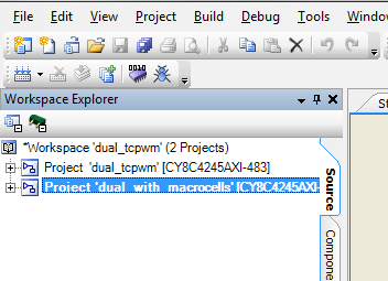
In the attached workspace contains two projects “Dual_TCPWM” and “Dual_with_macrocells”. Both of these examples address the challenge of creating two PWM outputs from a single PWM.
Dead Time-Based
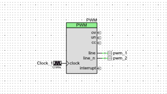
The first, purely firmware-based method relies on using dead time together with the TCPWM’s compare value and clever manipulation of the PWM’s output inversion to effectively decouple the TCPWM’s two outputs. Due to the reliance on dead time, this method is limited to periods of up to 255, as dead time is also limited to 255 counts.
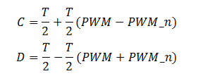
The positive PWM output follows the below equation:
Where C is TCPWM compare, D is dead time, and T is PWM period. The negative PWM output (PWM_n) follows the below equation:
Using these two equations, we can set up a system of equations that allows us to solve for the compare value and dead time for any configuration of PWM and PWM_n:
Reducing this matrix gives us the following for compare and dead time:
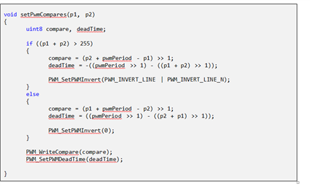
Unfortunately, though, this yields negative results for dead time when the two PWM densities sum to more than 1. To solve this problem, both outputs are negated, and the two input densities are switched before compare and dead time are calculated. The code below demonstrates how this technique would be used to configure a TCPWM PWM:
PLD-Based
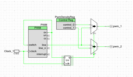
The PLD-based method relies on external logic and compare-swapping inside the TCPWM. This method allows 16-bit resolution, but uses 5 p-terms, 3 macrocells, and 2 control register bits.
This method uses the TCPWM’s OV output to trigger its own switch input, switching between its two compare registers. In this way, the output of the TCPWM is only driving one of the outputs at a given time, while the other is being driven by a control register.
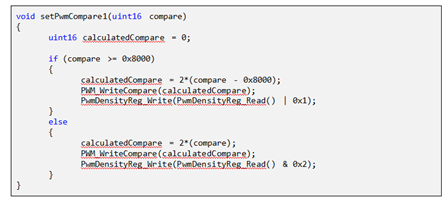
The control register is written with a 0 or 1 depending on the amplitude of the desired compare. The T flip flop automatically switches the mux so that the outputs are kept in sync. The code for configuring this TCPWM follows:
Hardware Connections:
There are no hardware connections for this example. We are showcasing how to create dual PWM outputs from a single PWM component. The user could connect to an o-scope to watch the output.
Test Your Project:
Program your example and connect the output pins to an o-scope to view the dual PWM ouputs.
I hope this example can help you in your design.
Best,
Matt

