


Hello!
Hello today we are going to go through a resistive touch example using the PSoC 4 pioneer kit. This example will interface custom hardware with the Pioneer kit. The pressure sensitive touch screen uses resistive force sensors distributed below the ‘Glass’ to measure applied force, which is analyzed to determine the press location.


Forum Post Attachments:
At the bottom of this post we are including the following items:
- Example Project Zip File
- Zip File of Images
- Project Schematic
- Component Configurations
Components Used:
The user can download the example project at the bottom of this post. The project uses the following list of Creator Components:
- UART
- Sar Sequencer
- ISR
- PWM
- CyPins
- CyClock
The components are configured by right clicking on the component in your Top Design schematic view and selecting Configure. Please enable the following selections in the Configuration windows for the listed components above.
Firmware Description:
The main.c firmware is included in the example project. Please review the commented sections for more details.
Force measurement can be very simple or very difficult depending on the constraints of your system. Were this an example for a cell phone, the sensors would need to be very small, screen printable, and cheap. Suitable technology for low cost sensors exists, but we chose to use a similar but more convenient force sensor.
Eight Flexiforce A301 sensors are placed underneath the ‘glass’, such that they support the weight. This ensures that no force escapes, and that the calculation made with this data will be accurate. A large source of error in these sorts of calculations is unplanned translational forces getting into the measurements, augmenting the location and force of the touch.

These force sensors, being essentially variable resistors, are measured with a half-bridge configuration. This configuration removes common mode noise, which is a significant portion of the noise in the measured signals. 10 kOhm resistors are used, as they were about the resistance of the sensor under the target loading. The middle of each bridge connection is connected to pins on the PSoC4 for measurement, through the Pioneer Kit’s J2 connector. The PSoC4 simply measures these signals with a sequencing SAR, with the bridge reference tied to the SAR’s reference input.
Calculation of the touch location is done using the SAR sequencer measurements and the known sensor locations. The following equations define the location of a single force applied to the screen. Yp is the vertical location of the touch, and Xp is the horizontal location of the touch.
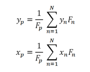
These equations are implemented in C, relying primarily on multiply-accumulates, and one divide. PSoC4’s CM0 core handles these calculations easily. The code for calculating touch location is shown below.

Also as part of this touch example we have provided a python GUI script that will display the XY position of the touches on your desk top. We have attached the script to this example. There is a video demonstration below that shows the touch panel in action. You will need a Python emulation environment to run this script. As a general note you may need to update this python script to point to the correct COM port created by the PSoC 5LP.
Hardware Connections:
The following schematic view capture provides the user the layout and values for the system. Please connect the breadboard or touch system to your PSoC 4 Pioneer kit.
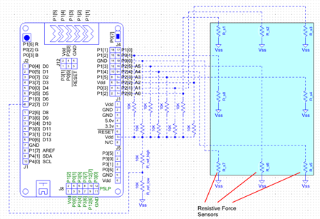
Also connect the PSoC 4 UART connections to the PSoC 5LP device so the UART positioning can be relayed up to the host.
PSoC 4 P4[1] -> P5LP P12[6]
PSoC 4 P4[0] -> P5LP P12[7]
Test Your Project:
Program the Pioneer kit and then touch the resistive touch panel you’ve created. Run the python script on your PC to read and display the values from the Pioneer kit. Please see an example of the system in action below.
I hope this example can help you in your design.
Best,
Matt


