element14 Community
element14 Community
    Register Log In
  • Site
  • Search
  • Log In Register
  • About Us
  • Community Hub
    Community Hub
    • What's New on element14
    • Feedback and Support
    • Benefits of Membership
    • Personal Blogs
    • Members Area
    • Achievement Levels
  • Learn
    Learn
    • Ask an Expert
    • eBooks
    • element14 presents
    • Learning Center
    • Tech Spotlight
    • STEM Academy
    • Webinars, Training and Events
    • Learning Groups
  • Technologies
    Technologies
    • 3D Printing
    • FPGA
    • Industrial Automation
    • Internet of Things
    • Power & Energy
    • Sensors
    • Technology Groups
  • Challenges & Projects
    Challenges & Projects
    • Design Challenges
    • element14 presents Projects
    • Project14
    • Arduino Projects
    • Raspberry Pi Projects
    • Project Groups
  • Products
    Products
    • Arduino
    • Avnet Boards Community
    • Dev Tools
    • Manufacturers
    • Multicomp Pro
    • Product Groups
    • Raspberry Pi
    • RoadTests & Reviews
  • Store
    Store
    • Visit Your Store
    • Choose another store...
      • Europe
      •  Austria (German)
      •  Belgium (Dutch, French)
      •  Bulgaria (Bulgarian)
      •  Czech Republic (Czech)
      •  Denmark (Danish)
      •  Estonia (Estonian)
      •  Finland (Finnish)
      •  France (French)
      •  Germany (German)
      •  Hungary (Hungarian)
      •  Ireland
      •  Israel
      •  Italy (Italian)
      •  Latvia (Latvian)
      •  
      •  Lithuania (Lithuanian)
      •  Netherlands (Dutch)
      •  Norway (Norwegian)
      •  Poland (Polish)
      •  Portugal (Portuguese)
      •  Romania (Romanian)
      •  Russia (Russian)
      •  Slovakia (Slovak)
      •  Slovenia (Slovenian)
      •  Spain (Spanish)
      •  Sweden (Swedish)
      •  Switzerland(German, French)
      •  Turkey (Turkish)
      •  United Kingdom
      • Asia Pacific
      •  Australia
      •  China
      •  Hong Kong
      •  India
      •  Korea (Korean)
      •  Malaysia
      •  New Zealand
      •  Philippines
      •  Singapore
      •  Taiwan
      •  Thailand (Thai)
      • Americas
      •  Brazil (Portuguese)
      •  Canada
      •  Mexico (Spanish)
      •  United States
      Can't find the country/region you're looking for? Visit our export site or find a local distributor.
  • Translate
  • Profile
  • Settings
Cypress Kits
  • Products
  • Dev Tools
  • Cypress Kits
  • More
  • Cancel
Cypress Kits
Forum PSoC 4 Pioneer Kit Community Project#089 – GPS Example
  • Blog
  • Forum
  • Documents
  • Polls
  • Files
  • Members
  • Mentions
  • Sub-Groups
  • Tags
  • More
  • Cancel
  • New
Join Cypress Kits to participate - click to join for free!
Actions
  • Share
  • More
  • Cancel
Forum Thread Details
  • Replies 5 replies
  • Subscribers 26 subscribers
  • Views 1892 views
  • Users 0 members are here
Related

PSoC 4 Pioneer Kit Community Project#089 – GPS Example

cy.wbz
cy.wbz over 12 years ago

Hello!


In today’s example we are building off of our earlier GPS example we posted this week. Today’s example uses the MediaTek GPS GTPA010 module. This module provides the built in GPS chip set and patch antenna on a PCB board. You can either purchase the  GPS module or a board from the PMOD folks.


For more information on the GPS data stream please have a look at the following Arduino GPS tutorial web page. On this web page they discuss the functionality of the GPS modules and the NMEA data structure. It can be helpful for people new to GPS and embedded designs targeting GPS modules.


Also note that you can directly connect the PSoC 5LP UART connections to the GPS module to view the output using a Hyperterminal program or use a third part GUI that reads GPS data over a COM port.


image


Forum Post Attachments:


At the bottom of this post we are including the following items:

  • Example Project Zip File
  • Project Images


Components Used: 


The user can download the example project at the bottom of this post. The project uses the following list of Creator Components:
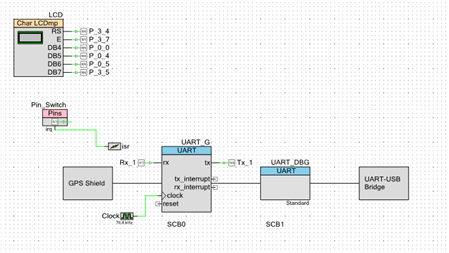
  • Char LCD
  • UART (x2)
  • CyPins
  • ISR
  • CyClock


Firmware Description:


The main.c firmware is included in the example project. Please review the commented sections for more details.


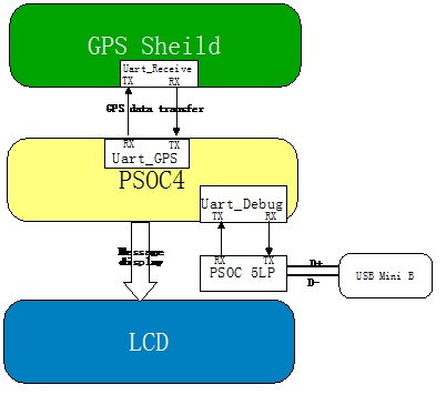
The firmware for this PSoC 4 example pulls in GPS data from the target GPS module and displays the parsed location on an LCD module. The PSoC 4 receives the GPS data via UART from the GPS module. The data packets received from the GPS module will be then displayed on an LCD screen.


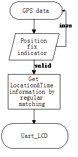
The following image is an example of the firmware flow. The firmware checks to see if a valid position fix is obtained. If a valid fix is found then the data is then parsed and displayed on the LCD module.


image


You will notice in the design we have left in the second UART component for any debug work you may want to conduct with the example. You can use the USB-UART on the PSoC 5LP to perform any debug work or visualization if you do not have an LCD module to plug into the example. Please see the example from the other day on how enable the debug UART. To use the debug UART you will need to de-comment certain sections of the example code.


image


Hardware Connections:


For this example the user will need to connect GPS module to the UART component outputs.


Next connect an LCD module using a bread board and wires. This section is not necessary since you can use the second UART in the example to send data using the USB-UART bridge on the Pioneer board and see that data using a hyperterminal application.


Test Your Project:


Program the example into the Pioneer board. Connect the UART to the GPS module. View the data displayed on the LCD or view the data sent over the UART bridge.


I hope this example can help you in your design.


Best,

Matt

Attachments:
project_GPS.zip
2548.Project Images.zip
  • Sign in to reply
  • Cancel
  • Former Member
    Former Member over 11 years ago

    Do you have a schematic of how you connected your GPS to the PSoC4?  The specific GPS that I have is a LINX RXM-GPS-RM.  At first, I only connected the VCC (VIN), Ground, RX and TX (UART).  I then made a simple program that polls the GOS data every once a second and displays it on an LCD.  I am not getting any values, just gibberish.  I checked my connections, the baud speed, and some other potential issues and everything seems okay.  The only think I can think of is that maybe because I have not done anything with the  VBACKUP, ON_OFF, and/or RESET the GPS module is not operational.  I would like to see how you have it wired and make sure that I am following suit.  Thanks. 

    Thanks,

    Justin 

    • Cancel
    • Vote Up 0 Vote Down
    • Sign in to reply
    • Cancel
  • Former Member
    Former Member over 10 years ago

    I am new to PSoC 4. I am trying to interface GPS to PSoC 4. I am using PSoC Creator 3.1 Component Pack 1. In the above example  component of LCD used is CharacterLCD  v1.2  which is absolute in PSoC Creator 3.1 Component Pack 1 (newer component is Character LCD v2.10). The newer version does not allow to use the random pins as shown in the .cysch file. It allows only the set of pins on the same port.       So how do I solve this problem???  


    Still I have loaded the above given code into the pioneer board. I did the hardware connections for USB-Serial bridge for debugging (and to see on hyperterminal) and the LCD connections. I get "GPS Shield" only on hyperterminal but nothing on the LCD (LCD too should display "GPS Shield"). The further code does not work at all.

    What do I do???


    Any prompt and quicker help will be appreciated.


    Regards,

    Sarang


    • Cancel
    • Vote Up 0 Vote Down
    • Sign in to reply
    • Cancel
  • clem57
    clem57 over 10 years ago in reply to Former Member

    @people/sarangsury

         I would try to build code just for the LCD in question only at this point. Please show a picture of the wiring and a list of hardware used in particular the LCD. Did you look at the datasheet? Sometimes they will update them and change just a little(the thing that may affect the code).


    Cheers,

    Clem

    • Cancel
    • Vote Up 0 Vote Down
    • Sign in to reply
    • Cancel
  • Former Member
    Former Member over 10 years ago in reply to clem57

    hey clem any further report.


    Regards,

    Sarang

    • Cancel
    • Vote Up 0 Vote Down
    • Sign in to reply
    • Cancel
  • Former Member
    Former Member over 10 years ago

    Hello Matthew,


    I think,

    In .cydwr file Rx_1 pin is connected to P3[1] (uart_tx) which actually should be P3[0] (uart_rx).


    Otherway round should be for Tx_1 pin.


    Regards,

    Sarang

    • Cancel
    • Vote Up 0 Vote Down
    • Sign in to reply
    • Cancel
element14 Community

element14 is the first online community specifically for engineers. Connect with your peers and get expert answers to your questions.

  • Members
  • Learn
  • Technologies
  • Challenges & Projects
  • Products
  • Store
  • About Us
  • Feedback & Support
  • FAQs
  • Terms of Use
  • Privacy Policy
  • Legal and Copyright Notices
  • Sitemap
  • Cookies

An Avnet Company © 2025 Premier Farnell Limited. All Rights Reserved.

Premier Farnell Ltd, registered in England and Wales (no 00876412), registered office: Farnell House, Forge Lane, Leeds LS12 2NE.

ICP 备案号 10220084.

Follow element14

  • X
  • Facebook
  • linkedin
  • YouTube