element14 Community
element14 Community
    Register Log In
  • Site
  • Search
  • Log In Register
  • About Us
  • Community Hub
    Community Hub
    • What's New on element14
    • Feedback and Support
    • Benefits of Membership
    • Personal Blogs
    • Members Area
    • Achievement Levels
  • Learn
    Learn
    • Ask an Expert
    • eBooks
    • element14 presents
    • Learning Center
    • Tech Spotlight
    • STEM Academy
    • Webinars, Training and Events
    • Learning Groups
  • Technologies
    Technologies
    • 3D Printing
    • FPGA
    • Industrial Automation
    • Internet of Things
    • Power & Energy
    • Sensors
    • Technology Groups
  • Challenges & Projects
    Challenges & Projects
    • Design Challenges
    • element14 presents Projects
    • Project14
    • Arduino Projects
    • Raspberry Pi Projects
    • Project Groups
  • Products
    Products
    • Arduino
    • Avnet Boards Community
    • Dev Tools
    • Manufacturers
    • Multicomp Pro
    • Product Groups
    • Raspberry Pi
    • RoadTests & Reviews
  • Store
    Store
    • Visit Your Store
    • Choose another store...
      • Europe
      •  Austria (German)
      •  Belgium (Dutch, French)
      •  Bulgaria (Bulgarian)
      •  Czech Republic (Czech)
      •  Denmark (Danish)
      •  Estonia (Estonian)
      •  Finland (Finnish)
      •  France (French)
      •  Germany (German)
      •  Hungary (Hungarian)
      •  Ireland
      •  Israel
      •  Italy (Italian)
      •  Latvia (Latvian)
      •  
      •  Lithuania (Lithuanian)
      •  Netherlands (Dutch)
      •  Norway (Norwegian)
      •  Poland (Polish)
      •  Portugal (Portuguese)
      •  Romania (Romanian)
      •  Russia (Russian)
      •  Slovakia (Slovak)
      •  Slovenia (Slovenian)
      •  Spain (Spanish)
      •  Sweden (Swedish)
      •  Switzerland(German, French)
      •  Turkey (Turkish)
      •  United Kingdom
      • Asia Pacific
      •  Australia
      •  China
      •  Hong Kong
      •  India
      •  Korea (Korean)
      •  Malaysia
      •  New Zealand
      •  Philippines
      •  Singapore
      •  Taiwan
      •  Thailand (Thai)
      • Americas
      •  Brazil (Portuguese)
      •  Canada
      •  Mexico (Spanish)
      •  United States
      Can't find the country/region you're looking for? Visit our export site or find a local distributor.
  • Translate
  • Profile
  • Settings
Cypress Kits
  • Products
  • Dev Tools
  • Cypress Kits
  • More
  • Cancel
Cypress Kits
Forum PSoC 4 Pioneer Kit Community Project#094 – Amplifier with Dynamic Gain Switching
  • Blog
  • Forum
  • Documents
  • Polls
  • Files
  • Members
  • Mentions
  • Sub-Groups
  • Tags
  • More
  • Cancel
  • New
Join Cypress Kits to participate - click to join for free!
Actions
  • Share
  • More
  • Cancel
Forum Thread Details
  • Replies 12 replies
  • Subscribers 30 subscribers
  • Views 3155 views
  • Users 0 members are here
Related

PSoC 4 Pioneer Kit Community Project#094 – Amplifier with Dynamic Gain Switching

cy.wbz
cy.wbz over 12 years ago

Hello!


In today’s example project we are continuing to explore more analog centric projects. In this example we are implementing a 3 channel amplifier with a dynamic gain switch. Based on your end design you may want to change the gain of your amplifier when reading in your analog signals. In this example we use a button selection to control the gain on the amplifier, but in your design you may change the gain by inputs from your system. The values are then sent over the UART port to be displayed on a Hyperterminal application.


image


Forum Post Attachments:


At the bottom of this post we are including the following items:

  • Example Project Zip File
  • Project Images


Components Used: 


The user can download the example project at the bottom of this post. The project uses the following list of Creator Components:

  • Amux
  • OpAmp
  • ADC SAR Seq
  • UART
  • Debouncer
  • CyClock
  • CyPins


Firmware Description:


The main.c firmware is included in the example project. Please review the commented sections for more details.


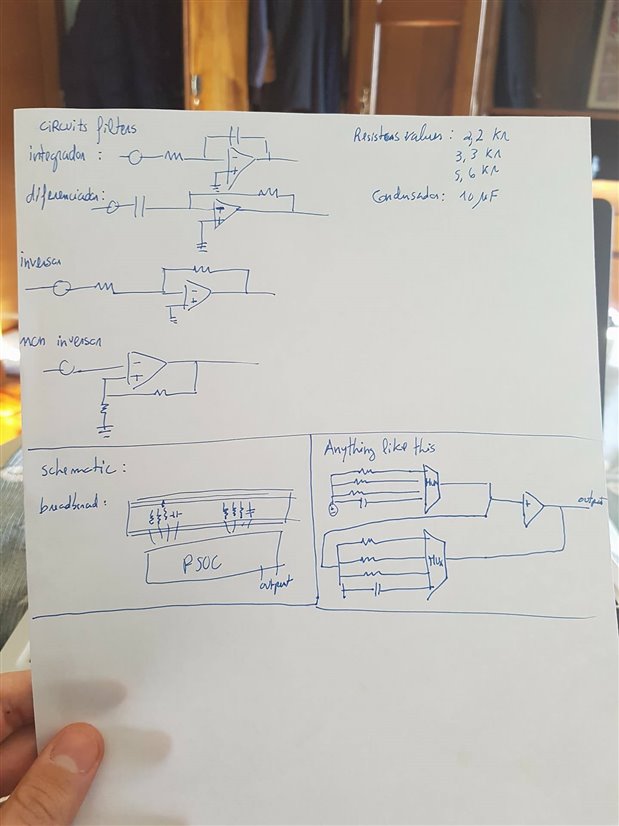
The Opamp is used to amplify the input signal. Selection of input channel is done using Input_Amux and selection of the Gain is done using the Gain_Amux. The UART is used to send ADC results through the UART bridge on the PSoC 5LP.


The Debouncer component is used to remove glitches from the input switch. The SAR ADC converts the analog output of the OpAmp into digital values. The ADC also generates an interrupt when its input is outside the defined voltage window (250mV-750mV). The LED is turned on when the ADC generates this interrupt.


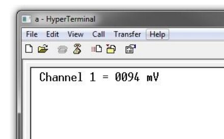
The data displayed over the UART includes the ADC output of the active channel along with the channel number to the HyperTerminal.


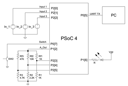
Hardware Connections:


The external hardware connections for this example are detailed in the schematic capture for this project. We include the external components and layout information using the annotated components. These annotated components detail the various resistor values needed to control the variable gain amplifier.


image


Test Your Project:


Program the Pioneer board and connect your three input signals. Then connect the UART to the PSoC 5LP and launch the hyperterminal software to view the UART output.


image


I hope this example can help you in your design.


Best,

Matt

Attachments:
5187.Project Images.zip
Opamp_Dynamic_Gain_Switching01.zip
  • Sign in to reply
  • Cancel

Top Replies

  • hlipka
    hlipka over 12 years ago +1
    Just as a note: PSoC3 and 5 contain an internal PGA, so they canswitch gain even without external components.
  • michaelkellett
    michaelkellett over 7 years ago in reply to eduardosilva +1
    No need to pay and no need to use Psoc or to panic. There are loads and loads of analogue switch chips on the market. I can help you choose if you post a schematic showing, or you can choose yourself.…
Parents
  • hlipka
    hlipka over 12 years ago

    Just as a note: PSoC3 and 5 contain an internal PGA, so they canswitch gain even without external components.

    • Cancel
    • Vote Up +1 Vote Down
    • Sign in to reply
    • Cancel
Reply
  • hlipka
    hlipka over 12 years ago

    Just as a note: PSoC3 and 5 contain an internal PGA, so they canswitch gain even without external components.

    • Cancel
    • Vote Up +1 Vote Down
    • Sign in to reply
    • Cancel
Children
  • cy.gul
    cy.gul over 12 years ago in reply to hlipka

    good point, Hendrik.


    Our larger 32-bit ARM Cortex-M3 PSoC 5LP devices (and the 8-bit PSoC 3) have internal programmable gain amplifiers, including an internal resistor ladder to chose different gain values.


    On PSoC 4, you can achive a similar design with internal MUXes and external resistors as shown in this design.

    • Cancel
    • Vote Up 0 Vote Down
    • Sign in to reply
    • Cancel
  • eduardosilva
    eduardosilva over 7 years ago in reply to cy.gul

    what values for the inputs?

    • Cancel
    • Vote Up 0 Vote Down
    • Sign in to reply
    • Cancel
  • koudelad
    koudelad over 7 years ago in reply to eduardosilva

    Values of what?


    If you mean the input voltage, all is limited by the ADC and the gain of the op-amp. The ADC for PSoC 4200 family (see the datasheet, section Analog Blocks) has an operating range of 1,71 V to 5,5 V (which should correspond with the voltage powering the PSoC). The gain of the op-amp is according to the schematics above set by the resistors to three possible levels, 2, 5,54 and 11. Divide the operating voltage of the ADC by the selected gain and you get an upper bound of the input. The lower bound is the same as Vcc of the microcontroller (in this case), which is 0 V.

    • Cancel
    • Vote Up 0 Vote Down
    • Sign in to reply
    • Cancel
  • eduardosilva
    eduardosilva over 7 years ago in reply to koudelad

    Hello, thank you for the information!


    Look I'm a student, and i have a final project to do for the university.


    Here, we never work with PSOC, so i dont know very much about this. So, i'm trying to do some examples to learn.

    In my project I have 4 analogic filters ( integrador, diferenciador, inversor, no inversor ), and i need to multiplexing the resistors to do a remote lab, with labview help!


    So, in this moment I'm kind desperated, so any angel can help me with this project? (I pay if it's necessary) image


    Best regards,

    • Cancel
    • Vote Up 0 Vote Down
    • Sign in to reply
    • Cancel
  • michaelkellett
    michaelkellett over 7 years ago in reply to eduardosilva

    No need to pay and no need to use Psoc or to panic.


    There are loads and loads of analogue switch chips on the market.


    I can help you choose if you post a schematic showing, or you can choose yourself.


    If you choose yourself look out for the maximum size of signals the switch can handle, the on resistance, the leakage current and the stray capacity. You'll need to decide if you want to use multiplexers or switches or a combination.


    Look at TI  and Analogue Devices websites.


    Modern parts will come in SM packages (and some have very low operating voltages but otherwise very good specs).


    MK

    • Cancel
    • Vote Up +1 Vote Down
    • Sign in to reply
    • Cancel
  • eduardosilva
    eduardosilva over 7 years ago in reply to michaelkellett

    Can anyone send me a adress to Talk about this, and send schematics etc


    Or I put it here?


    I have some questions about this part of project.


    Best regards friends

    • Cancel
    • Vote Up 0 Vote Down
    • Sign in to reply
    • Cancel
  • michaelkellett
    michaelkellett over 7 years ago in reply to eduardosilva

    Just post here, use the 7th icon along to insert a picture.


    MK

    • Cancel
    • Vote Up 0 Vote Down
    • Sign in to reply
    • Cancel
  • eduardosilva
    eduardosilva over 7 years ago in reply to michaelkellett

    image


    Hello friends.
    I leave here some items that I need for this final project.

    I need to multiplex the various filters.
    I do not know how to control the multiplexers, since I'm supposed to receive some characters from the client that will define which filter to use.

    Along with Psoc I will also use an elvis ni, and the labview.

    Any angel that can help me with this part of Psoc at least?
    I'm a bit desperate, please some help.
    Thanks for listening!

    Best regards, dear friends
    Any more pics, please report

    • Cancel
    • Vote Up 0 Vote Down
    • Sign in to reply
    • Cancel
  • michaelkellett
    michaelkellett over 7 years ago in reply to eduardosilva

    You'll need a Psoc user to help with Psoc specific stuff, do you have to use a Psoc or can you use any micro and some external hardware ?.


    Looks to me as if you need a dual 4 way analogue multiplexer - lots around - no problem. You component choice is bad - good quality 10uF capacitors are very big and very expensive, for filters you should use film capacitors or COG/NPO type ceramics. High value ceramic capacitors are very voltage dependent so introduce distortion.

    If you made the capacitors 1uF 63V film types you could scale the resistors up by a factor of 10 and have the same filter frequencies, but with sensible size of capacitors.

    BTW, that integrator looks worrying - there is no DC feedback on the amplifier so it will sit with its output at one rail or the other - perhaps you haven't shown us the complete circuit.


    Let me know if you have to use Psoc and if not I'll try to sketch out how to use the multiplexers. Do you have a design spec for the whole thing, and what is it for ?


    MK

    • Cancel
    • Vote Up 0 Vote Down
    • Sign in to reply
    • Cancel
  • eduardosilva
    eduardosilva over 7 years ago in reply to michaelkellett

    Good afternoon MK,

    Yes the final project of the university, consists of the use of the PSOC to carry out this work.

    I just needed some help with this part of Psoc, someone who could sketch something for me in Psoc, who understands how multiplexers work and how to do their control.

    As for the values of the compenents this is adaptable, and is not the most relevant. The integrator circuit is just the same.

    If someone could help me please ..

    Best wishes, friends,

    • Cancel
    • Vote Up 0 Vote Down
    • Sign in to reply
    • Cancel
element14 Community

element14 is the first online community specifically for engineers. Connect with your peers and get expert answers to your questions.

  • Members
  • Learn
  • Technologies
  • Challenges & Projects
  • Products
  • Store
  • About Us
  • Feedback & Support
  • FAQs
  • Terms of Use
  • Privacy Policy
  • Legal and Copyright Notices
  • Sitemap
  • Cookies

An Avnet Company © 2025 Premier Farnell Limited. All Rights Reserved.

Premier Farnell Ltd, registered in England and Wales (no 00876412), registered office: Farnell House, Forge Lane, Leeds LS12 2NE.

ICP 备案号 10220084.

Follow element14

  • X
  • Facebook
  • linkedin
  • YouTube