element14 Community
element14 Community
    Register Log In
  • Site
  • Search
  • Log In Register
  • About Us
  • Community Hub
    Community Hub
    • What's New on element14
    • Feedback and Support
    • Benefits of Membership
    • Personal Blogs
    • Members Area
    • Achievement Levels
  • Learn
    Learn
    • Ask an Expert
    • eBooks
    • element14 presents
    • Learning Center
    • Tech Spotlight
    • STEM Academy
    • Webinars, Training and Events
    • Learning Groups
  • Technologies
    Technologies
    • 3D Printing
    • FPGA
    • Industrial Automation
    • Internet of Things
    • Power & Energy
    • Sensors
    • Technology Groups
  • Challenges & Projects
    Challenges & Projects
    • Design Challenges
    • element14 presents Projects
    • Project14
    • Arduino Projects
    • Raspberry Pi Projects
    • Project Groups
  • Products
    Products
    • Arduino
    • Avnet Boards Community
    • Dev Tools
    • Manufacturers
    • Multicomp Pro
    • Product Groups
    • Raspberry Pi
    • RoadTests & Reviews
  • Store
    Store
    • Visit Your Store
    • Choose another store...
      • Europe
      •  Austria (German)
      •  Belgium (Dutch, French)
      •  Bulgaria (Bulgarian)
      •  Czech Republic (Czech)
      •  Denmark (Danish)
      •  Estonia (Estonian)
      •  Finland (Finnish)
      •  France (French)
      •  Germany (German)
      •  Hungary (Hungarian)
      •  Ireland
      •  Israel
      •  Italy (Italian)
      •  Latvia (Latvian)
      •  
      •  Lithuania (Lithuanian)
      •  Netherlands (Dutch)
      •  Norway (Norwegian)
      •  Poland (Polish)
      •  Portugal (Portuguese)
      •  Romania (Romanian)
      •  Russia (Russian)
      •  Slovakia (Slovak)
      •  Slovenia (Slovenian)
      •  Spain (Spanish)
      •  Sweden (Swedish)
      •  Switzerland(German, French)
      •  Turkey (Turkish)
      •  United Kingdom
      • Asia Pacific
      •  Australia
      •  China
      •  Hong Kong
      •  India
      •  Korea (Korean)
      •  Malaysia
      •  New Zealand
      •  Philippines
      •  Singapore
      •  Taiwan
      •  Thailand (Thai)
      • Americas
      •  Brazil (Portuguese)
      •  Canada
      •  Mexico (Spanish)
      •  United States
      Can't find the country/region you're looking for? Visit our export site or find a local distributor.
  • Translate
  • Profile
  • Settings
Cypress Kits
  • Products
  • Dev Tools
  • Cypress Kits
  • More
  • Cancel
Cypress Kits
Forum PSoC 5LP Programmer Firmware
  • Blog
  • Forum
  • Documents
  • Polls
  • Files
  • Members
  • Mentions
  • Sub-Groups
  • Tags
  • More
  • Cancel
  • New
Join Cypress Kits to participate - click to join for free!
Actions
  • Share
  • More
  • Cancel
Forum Thread Details
  • Replies 27 replies
  • Subscribers 32 subscribers
  • Views 7242 views
  • Users 0 members are here
Related

PSoC 5LP Programmer Firmware

cy.wbz
cy.wbz over 12 years ago

Hello!


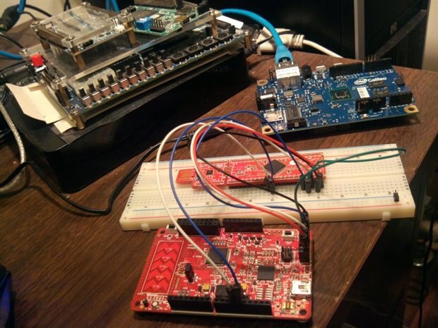
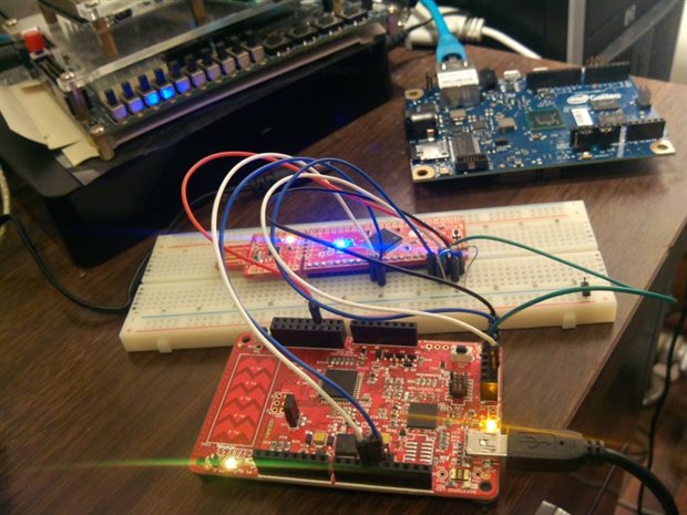
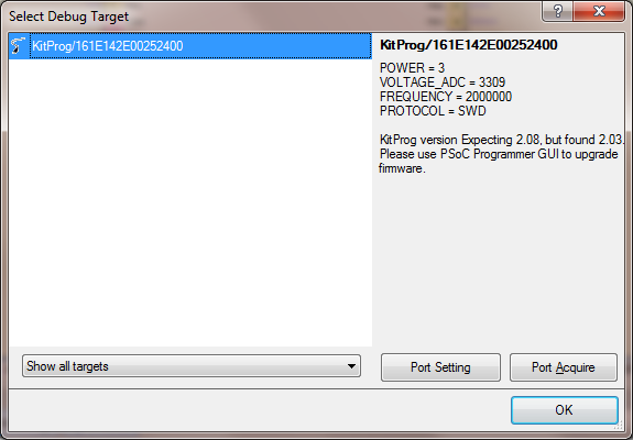
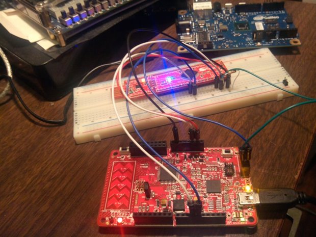
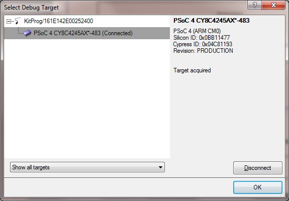
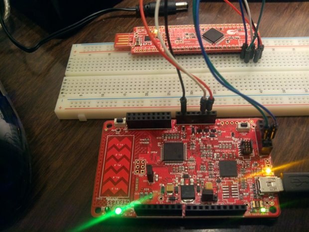
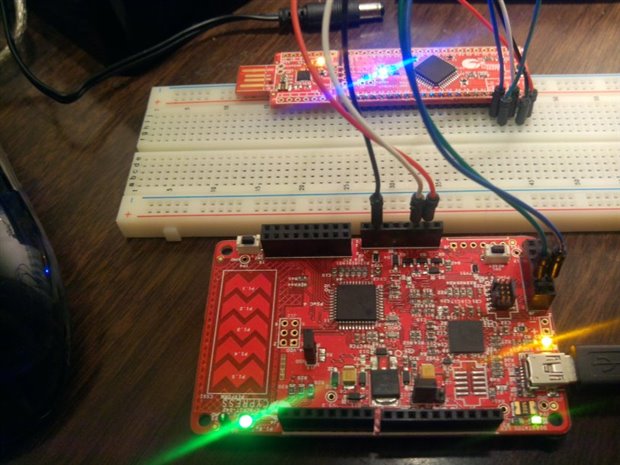
Today I would like to post an extra project for you guys. Attached to this post is the firmware for the PSoC 5LP device on the Pioneer kit. If you are designing a board and need a programmer and debugger for the board feel free to copy the PSoC 5LP layout on the Pioneer board and use this firmware to enable programming and debugging. The layout files are on the Cypress Pioneer Kit web page:


www.cypress.com/cy8ckit-042


This will allow you interface your custom board with our PSoC Creator and PSoC Programmer development tools.


In the example attached we have two projects, the source code for the PSoC 5LP and a base bootloadable project. To build the project you will need to perform the following actions:


1. Make the project KitProg_Bootloader active and build it first.

2. Open the KitProg project TopDesign.

3. Doube click the bootloadable component to open the bootloadable configuration.

4. Select the tab 'dependencies' and select the browse button.

5. Browse to the folder where the KitProg Bootloader.hex file is generated and select this file. Click Ok.


Good Luck!

Matt

Attachments:
KitProg version 2_03.zip
  • Sign in to reply
  • Cancel

Top Replies

  • Former Member
    Former Member over 11 years ago in reply to Former Member +2
    The other day I found a little SOIC 0.65 pitch board (schmartboard) so I used one of my 4200 SSOP 28 pin chips. I bought 10 SSOPs 10 QFPs and 20 QFN while they were (and still are) a dollar a pop. I had…
  • Former Member
    Former Member over 12 years ago +1
    Wow~ That's cool~
  • Former Member
    Former Member over 11 years ago +1
    Hi all, Posting the PSoC 5LP firmware updated for PSoC Creator 3.0 -Ranjith Attachments: community.element14.com/.../KitProg.zip
Parents
  • Former Member
    Former Member over 11 years ago

    So I got this compiled and working on Creator 3.0 upgrading booloader and bootable to only 1.10 and not letting USBFS upgrade at all.

    Now I'm trying to use this and redirect the programming output to use the 5LP 12 pin header. Mapped xres_n to P0.0, SWDCLK to P3.4, SWDIO to P3.6.

    I used the same configuration to modify AN84858 to program a 4200 prototype board (the $4 ones). using the included C# to create the HexImage file out of a .hex bootloadable program, that I couldn't program before because I did run the default AN84858 code that removed the bootloader.


    But I want to take it a step further to be able to use the pioneer as a debugger for an external PSoC 4200. The kitprog shows up but it doesn't find the PSoC 4 chip, even if the modified AN84858 can program it just fine. I also connected the Pioneer PSoC P3.0 and P3.1 to the prototype board P3.0 and P3.1 respectively for the I2C communication since in the pioneer they are connected to the 5LP P12.0 and P12.1 as shown in page 102 of the pioneer manual (awesome work btw). The only thing the prototype board doesn't have that the Pioneer does is XRES in the pioneer is pulled high to P4_VDD with a 4.7K resistor shown in page 101 and I'm using P5LP_VDD instead of the P4_VDD but that will be easy to do since it's available in pin 6 of J2.


    The prototype chip has the same chip (CY8C4245AXI-483 44TQFP) as the Pioneer one.


    So I'm going to try to put a 4.7K resistor between XRES and P4_VDD on my breadboard, but I doubt that's all it takes.

    Am I missing anything obvious?

    image

    • Cancel
    • Vote Up 0 Vote Down
    • Sign in to reply
    • Cancel
  • Former Member
    Former Member over 11 years ago in reply to Former Member

    So I moved from the 5LP_VDD to the P4_VDD and added a 4.7K resistor between /XRES and P4_VDD

    image

    The prototype board runs it's blinking bootable program, but KitProg can't see the chip.

    @image

    I remember somewhere in the project that it forced contiguous pins, can that be the reason?

    Like using P3.4 and P3.5 in the 5LP instead of P3.4 and P3.6 for the SWDCLK and SWDIO?


    Edit: I know the MiniProg 3 will solve my issue, but for $90 I can get more dev kits instead of programming ones.

    I have 40 PSoC for a project that of course I can program now with the altered AN84858 Pioneer code.

    10 QFPs 10 SSOPs and 20 QFNs, the last ones I ordered by mistake, but the thing is I would love to build a prototype board of my own and use the Pioneer as a programmer/debugger. I can do the programmer but not the debugger.


    I'm also aware about using the $4 prototype boards as programmers but I would love to do the debugging as well without purchasing the MiniProg 3B which I should probably get anyways.

    • Cancel
    • Vote Up 0 Vote Down
    • Sign in to reply
    • Cancel
  • Former Member
    Former Member over 11 years ago in reply to Former Member

    Success:


    I connected the Pioneer's PSoC 4 P3_0, P3_1, GND, P4_VDD & /XRES to the same pins in the prototype kit.

    For SWDIO and SWDCLK used the PSoC 5LP P0_0 and P0_1 and connected those to the prototype board.

    I only had to change the ProgKit pinout for SWDIO from P5LP2_0 to P5LP0_0  and SWDCLK from P5LP2_1 to P5LP0_1 and wired it as shown here:

    image


    Now I can use program directly from Creator 3.0 and if I open Debug/Select Debug Target... I get the KitProg with the chip enumerated within it.

    image

    Finally I was able to attach to the running program or debug it from scratch and set a Breakpoint

    image


    Thank you for making the KitProg source available! image


    Edit: I was too hasty about debugging from scratch, but I can however attach to the running project and put breakpoints after attaching, will investigate further about being able to use F5 to debug from scratch. Also P3_0 and P3_1 don't seem to be needed, and the pull-up resistor probably can go away as well.

    • Cancel
    • Vote Up 0 Vote Down
    • Sign in to reply
    • Cancel
  • Former Member
    Former Member over 11 years ago in reply to Former Member

    If the program is not bootloadable it has full debug, meaning you can press F5 and step through the code from main.

    image

    Of course I don't run it in such a small window, I resized the IDE to make it more post friendly image


    Excuse the mess of jumper wires, but this has the Pioneer debugging the prototype kit that runs a frequency counter (on the floating yellow wire on the left) that is picking up the 60Hz mains that is everywhere.

    The frequency counter code comes from this site:

    self.clue++ : Starting the PSoC frequency counter series


    image


    I overdid the contrast so it will show up in the camera. Also the thing on the right of the breadboard is two pots and a buzzer, i'm using one of the pots to adjust the contrast of the LCD screen. Although it could be controlled with and analog output pin and use capsense to adjust it.


    So it's acting like a MiniProg3 after all. Also I didn't need the pull up resistor nor the 2 wires for SPI, so it's a 5 wire programmer just like the MiniProg3.


    Also I don't have to care about removing the bootloader on the prototype kit since I can upload a bootloader anytime now.

    • Cancel
    • Vote Up +1 Vote Down
    • Sign in to reply
    • Cancel
Reply
  • Former Member
    Former Member over 11 years ago in reply to Former Member

    If the program is not bootloadable it has full debug, meaning you can press F5 and step through the code from main.

    image

    Of course I don't run it in such a small window, I resized the IDE to make it more post friendly image


    Excuse the mess of jumper wires, but this has the Pioneer debugging the prototype kit that runs a frequency counter (on the floating yellow wire on the left) that is picking up the 60Hz mains that is everywhere.

    The frequency counter code comes from this site:

    self.clue++ : Starting the PSoC frequency counter series


    image


    I overdid the contrast so it will show up in the camera. Also the thing on the right of the breadboard is two pots and a buzzer, i'm using one of the pots to adjust the contrast of the LCD screen. Although it could be controlled with and analog output pin and use capsense to adjust it.


    So it's acting like a MiniProg3 after all. Also I didn't need the pull up resistor nor the 2 wires for SPI, so it's a 5 wire programmer just like the MiniProg3.


    Also I don't have to care about removing the bootloader on the prototype kit since I can upload a bootloader anytime now.

    • Cancel
    • Vote Up +1 Vote Down
    • Sign in to reply
    • Cancel
Children
  • Former Member
    Former Member over 11 years ago in reply to Former Member

    So that there is no doubt, other than the 4200 $4 prototype kit I have a 4100 $4 prototype kit as well.


    I soldered one set of male headers like I did on the previous one and hooked it up to the breadboard and fired it up.

    image


    The 4100 chip showed up under the KitProg:

    image


    Also I was able to acquire it:

    image

    And program it with a bootloadable image, and of course you can program and debug it the same as the Pioneer built in 4200. Note the capsense pionner RGB demo is still running in the built in 4200 I just did touch the slider to turn it green instead of red. The 4100 has the blinky bootloadable demo but I could use it to display something on the LCD, but no analog so I didn't bother.


    image

    If you want more detailed connections or explanations (I would think it's clear enough if you look at the schematics), let me know in this thread. a thumbs up will help too even if the hard work was really done by the hard working folks from Cypress. I just rewired 2 pins!


    I don't have access to PSoC 3 boards or PSoC 5LP ones either, nor the original PSoC 1. So I don't know if they will enumerate right, I don't see why not but I didn't look deep in the code. I do however have 40 4200 chips for a small project in all three packages (QFN, TQFP & SSOP) that I intend to use the Pioneer to program them.


    Edit: this should work for the 4000 chips as well.

    • Cancel
    • Vote Up +1 Vote Down
    • Sign in to reply
    • Cancel
element14 Community

element14 is the first online community specifically for engineers. Connect with your peers and get expert answers to your questions.

  • Members
  • Learn
  • Technologies
  • Challenges & Projects
  • Products
  • Store
  • About Us
  • Feedback & Support
  • FAQs
  • Terms of Use
  • Privacy Policy
  • Legal and Copyright Notices
  • Sitemap
  • Cookies

An Avnet Company © 2025 Premier Farnell Limited. All Rights Reserved.

Premier Farnell Ltd, registered in England and Wales (no 00876412), registered office: Farnell House, Forge Lane, Leeds LS12 2NE.

ICP 备案号 10220084.

Follow element14

  • X
  • Facebook
  • linkedin
  • YouTube