element14 Community
element14 Community
    Register Log In
  • Site
  • Search
  • Log In Register
  • About Us
  • Community Hub
    Community Hub
    • What's New on element14
    • Feedback and Support
    • Benefits of Membership
    • Personal Blogs
    • Members Area
    • Achievement Levels
  • Learn
    Learn
    • Ask an Expert
    • eBooks
    • element14 presents
    • Learning Center
    • Tech Spotlight
    • STEM Academy
    • Webinars, Training and Events
    • Learning Groups
  • Technologies
    Technologies
    • 3D Printing
    • FPGA
    • Industrial Automation
    • Internet of Things
    • Power & Energy
    • Sensors
    • Technology Groups
  • Challenges & Projects
    Challenges & Projects
    • Design Challenges
    • element14 presents Projects
    • Project14
    • Arduino Projects
    • Raspberry Pi Projects
    • Project Groups
  • Products
    Products
    • Arduino
    • Avnet Boards Community
    • Dev Tools
    • Manufacturers
    • Multicomp Pro
    • Product Groups
    • Raspberry Pi
    • RoadTests & Reviews
  • Store
    Store
    • Visit Your Store
    • Choose another store...
      • Europe
      •  Austria (German)
      •  Belgium (Dutch, French)
      •  Bulgaria (Bulgarian)
      •  Czech Republic (Czech)
      •  Denmark (Danish)
      •  Estonia (Estonian)
      •  Finland (Finnish)
      •  France (French)
      •  Germany (German)
      •  Hungary (Hungarian)
      •  Ireland
      •  Israel
      •  Italy (Italian)
      •  Latvia (Latvian)
      •  
      •  Lithuania (Lithuanian)
      •  Netherlands (Dutch)
      •  Norway (Norwegian)
      •  Poland (Polish)
      •  Portugal (Portuguese)
      •  Romania (Romanian)
      •  Russia (Russian)
      •  Slovakia (Slovak)
      •  Slovenia (Slovenian)
      •  Spain (Spanish)
      •  Sweden (Swedish)
      •  Switzerland(German, French)
      •  Turkey (Turkish)
      •  United Kingdom
      • Asia Pacific
      •  Australia
      •  China
      •  Hong Kong
      •  India
      •  Korea (Korean)
      •  Malaysia
      •  New Zealand
      •  Philippines
      •  Singapore
      •  Taiwan
      •  Thailand (Thai)
      • Americas
      •  Brazil (Portuguese)
      •  Canada
      •  Mexico (Spanish)
      •  United States
      Can't find the country/region you're looking for? Visit our export site or find a local distributor.
  • Translate
  • Profile
  • Settings
Cypress Kits
  • Products
  • Dev Tools
  • Cypress Kits
  • More
  • Cancel
Cypress Kits
Forum PSOC 4 Ball and Beam Control System, identification toolbox.
  • Blog
  • Forum
  • Documents
  • Polls
  • Files
  • Members
  • Mentions
  • Sub-Groups
  • Tags
  • More
  • Cancel
  • New
Join Cypress Kits to participate - click to join for free!
Actions
  • Share
  • More
  • Cancel
Forum Thread Details
  • State Suggested Answer
  • Replies 33 replies
  • Answers 2 answers
  • Subscribers 28 subscribers
  • Views 4261 views
  • Users 0 members are here
  • psoc4
  • ballandbeam
  • identification
  • controlsystem
  • uart
  • pid
Related

PSOC 4 Ball and Beam Control System, identification toolbox.

juanes.pazj
juanes.pazj over 10 years ago

Short Review:

I have been working on this model for a while now, I was having some trouble with the sensor data but all of that is good now,

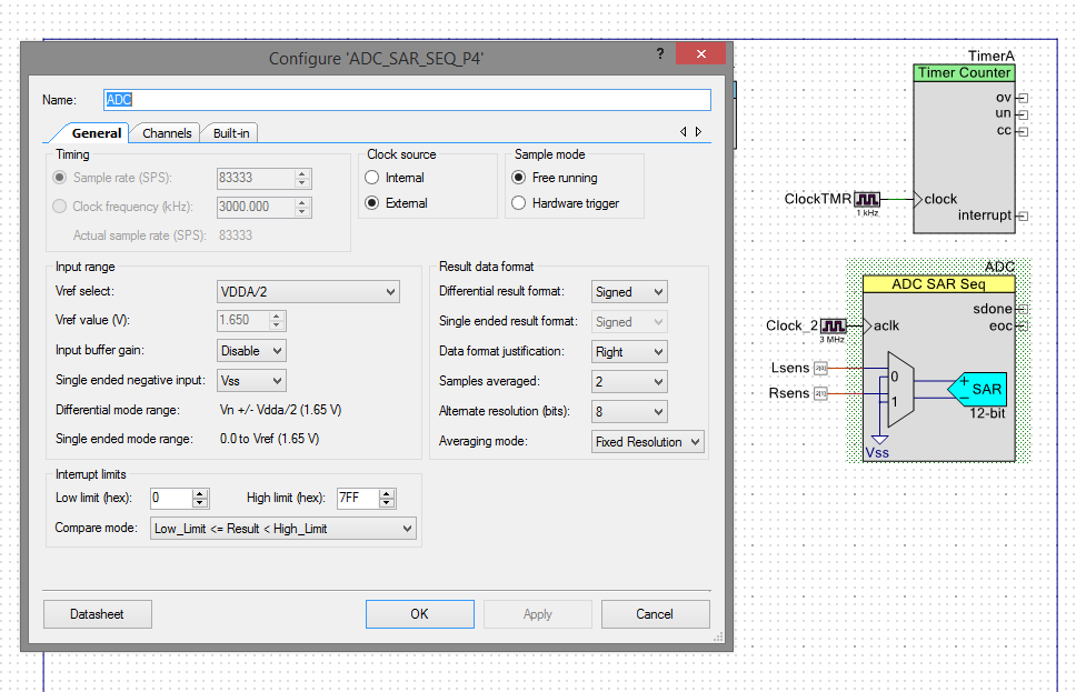
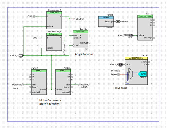
Here is how the system works every command is fed through the UART interface as well as data read from sensors or input data.

I managed to control angle only (motor position) although I am not very happy with it is somewhat unstable...

The trouble I am facing is controlling the ball position, the simpler control system I could come up was a cascade PID, the problem is I cant get both plants right for simulation Voltage-Angle and Angle-Position, I wanted to get them with identification toolbox in matlab (I have a transfer function for the angle-position plant it is :.

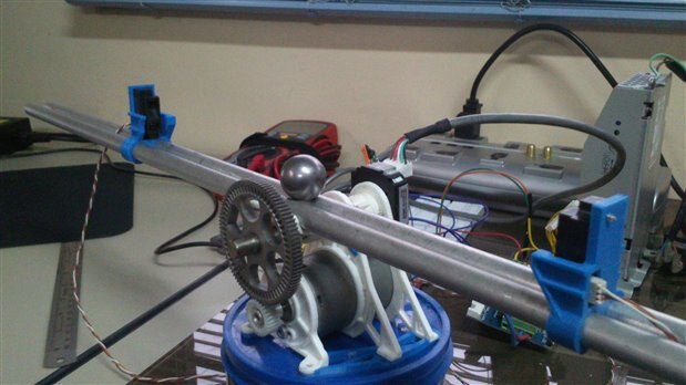
Since the motor was originally scrap from a printer I cant really get its parameters on a datasheet I know it is a Jhonson Motor, 36mm diameter 56mm length, 3mm shaft there are this numbers printed on it I can't seem to find any relation to a motor model. 65791, c5324-60024, 392361

image

image


I am not sure if the following procedure should have been the way to go for identification.

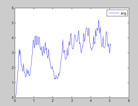
I made a Matlab Script that would read a word of data sent by the psoc through UART, in this format "a#p#t#x#f" so I get current angle, motor power (voltage%), current position, and time.

working with the time vector I managed to extract an average sampling time of 0.005s,

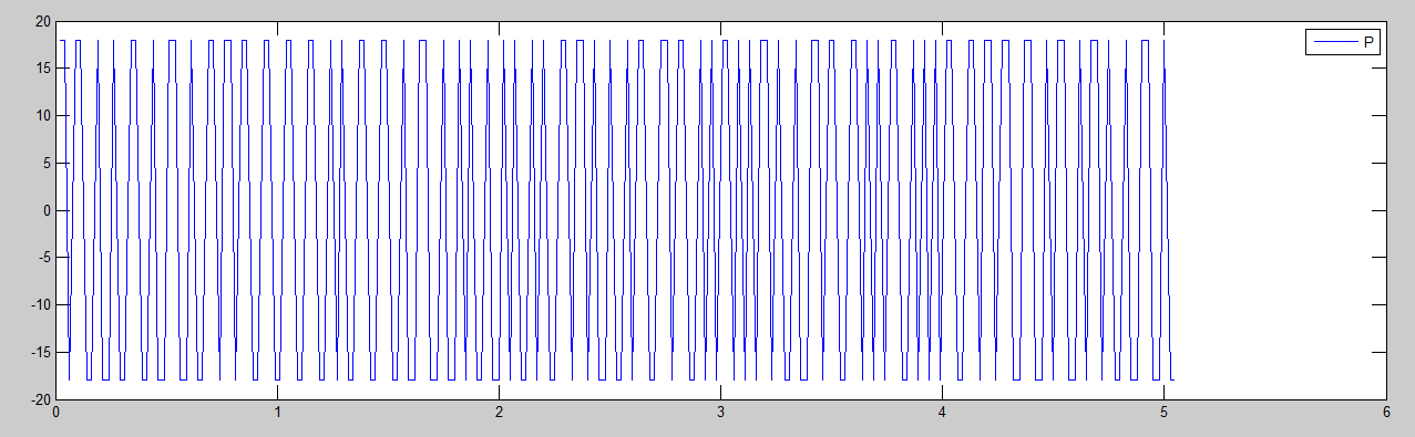
I had to create a PRBS signal to command the motor so I did it internally with two alternate power settings that are outputed on a random time (The plot doesnt make it a square wave but all the points are on +18 or -18.)

image

image

After this I went into Ident toolbox

after removing Means, trends and filtering and separating the data for evaluation and validation, I got a 97% fit with a box Jenkins (1 1 3 3 0) which should make a reliable model for simulation but If I used the PID parameters on the PSOC It would diverge every time I cant seem to find a solution.


I appreciate your help,

some questions..

the embedded system (PSOC) is very fast (the actual sampling time is 0.004s approximately, should I slow it down for the control system to work?? it Doesn't seem right.

All the theory says the PRBS signal should be 1,-1 signal How do I know if the PRBS signal's amplitude and width is good enough for identification??


I would like to try other control methods (non-linear) (State space) but I cant seem to get the models from identification.


I am not sure if the files are of any use without the model.. If you want to see them let me know.

Attachments:
RBBv2.cywrk.zip
  • Sign in to reply
  • Cancel

Top Replies

  • DAB
    DAB over 10 years ago +1
    Hi Juan, You are probably experiencing data lag time. When you try to correct something dynamic by using a measured position, you have to account for the movement of the object while you are calculating…
  • michaelkellett
    michaelkellett over 10 years ago in reply to juanes.pazj +1 suggested
    Do you have Simulink - if so you can model you controller and the system and the delays in the PSOC - this might be the quickest way to develop an algorithm/controller that works. MK
  • DAB
    DAB over 10 years ago +1
    Juan, I just remembered that the PSOC has an analog comparator as part of its programmable hardware. You can use that to provide near instantaneous correction for the balance circuitry. DAB
Parents
  • juanes.pazj
    0 juanes.pazj over 10 years ago

    Hey Guys,


    A problem I had with the UART interface is that the microcontroller didn't have enough memory to work with the SPRINTF routine (it would consume most of the program memory) so I had to write an itoa function which I think can be another cause of the slow sampling rate so I remembered I read about Rossserial a while ago.

    I was thinking should I try this out?

    Rosserial On Cypress PSoC4 - JR


    it is a Real time OS for embedded computing it should beat my UART interface speed.

    any thoughts?

    • Cancel
    • Vote Up 0 Vote Down
    • Sign in to reply
    • Verify Answer
    • Cancel
  • michaelkellett
    0 michaelkellett over 10 years ago in reply to juanes.pazj

    I may have missed something here - I'd thought you were just using the UART to dump acquired data to the PC. If the PC is in the control loop then you will find it almost impossible to get good control running under windows. If you are using  a USB adapter rather than a real hardware UART this will add lots of additional delay and timing jitter. If you are running at even 115200 baud then each additional character in your message adds 100us of delay - you can't afford to use ascii strings but should look at using a binary data format. Windows (or Linux) itself is not  a hard real time OS and will add even more delay and jitter.

    If you run the control loop on the PSOC you can avoid all this.


    MK

    • Cancel
    • Vote Up +1 Vote Down
    • Sign in to reply
    • Verify Answer
    • Cancel
  • juanes.pazj
    0 juanes.pazj over 10 years ago in reply to michaelkellett

    No no, UART just feeds data to see what is going on, the control loop is programed in the PSOC, I wanted to be able to work with identification by aquiring that data with the computer through matlab that is how I was able to measure the average sampling time

    • Cancel
    • Vote Up 0 Vote Down
    • Sign in to reply
    • Verify Answer
    • Cancel
  • michaelkellett
    0 michaelkellett over 10 years ago in reply to juanes.pazj

    Sorry - panicked a bit there - of course if it's just for monitoring then delays won't matter.


    Where did you put your code ?


    MK

    • Cancel
    • Vote Up +1 Vote Down
    • Sign in to reply
    • Verify Answer
    • Cancel
  • juanes.pazj
    0 juanes.pazj over 10 years ago in reply to michaelkellett

    haha no problem, I removed the simulink zip file and added RBBv2.cywrk.zip at the beggining

    • Cancel
    • Vote Up 0 Vote Down
    • Sign in to reply
    • Verify Answer
    • Cancel
  • michaelkellett
    0 michaelkellett over 10 years ago in reply to juanes.pazj

    I had a quick look at your code, it's going to be much quicker if you tell me the answers to the following rather than me try and work it out.


    How long does it take the processor to get round the loop and are the ADC conversions controlled by a timer so that the sampling rate is constant. What is the sampling rate ?


    MK

    • Cancel
    • Vote Up 0 Vote Down
    • Sign in to reply
    • Verify Answer
    • Cancel
  • juanes.pazj
    0 juanes.pazj over 10 years ago in reply to michaelkellett

    Via matlab uart i managed to get as low as 0.0036s average between messages

    not sure how should I measure that,

    The adc is setup with a 3mhz clock

    • Cancel
    • Vote Up 0 Vote Down
    • Sign in to reply
    • Verify Answer
    • Cancel
  • juanes.pazj
    0 juanes.pazj over 10 years ago in reply to juanes.pazj

    is there another way to measure the cycles or sampling rate?

    • Cancel
    • Vote Up 0 Vote Down
    • Sign in to reply
    • Verify Answer
    • Cancel
  • michaelkellett
    0 michaelkellett over 10 years ago in reply to juanes.pazj

    Yes, the only way I would recommend is that you add some code which sets a pin high when the ADC takes a sample and sets it low when the processing is finished. If the processing doesn't start immediately after the sample is available you may need to toggle the pin (or possibly two pins) twice.


    You then measure the rate and the jitter with an oscilloscope.


    Of course you should know the rate at  which the ADC is running from the software - are you triggering the adc from a timer or just running it as often as possible ?


    I would always design the code for  a constant and known sampling rate and then check with a 'scope.


    MK

    • Cancel
    • Vote Up 0 Vote Down
    • Sign in to reply
    • Verify Answer
    • Cancel
Reply
  • michaelkellett
    0 michaelkellett over 10 years ago in reply to juanes.pazj

    Yes, the only way I would recommend is that you add some code which sets a pin high when the ADC takes a sample and sets it low when the processing is finished. If the processing doesn't start immediately after the sample is available you may need to toggle the pin (or possibly two pins) twice.


    You then measure the rate and the jitter with an oscilloscope.


    Of course you should know the rate at  which the ADC is running from the software - are you triggering the adc from a timer or just running it as often as possible ?


    I would always design the code for  a constant and known sampling rate and then check with a 'scope.


    MK

    • Cancel
    • Vote Up 0 Vote Down
    • Sign in to reply
    • Verify Answer
    • Cancel
Children
  • juanes.pazj
    0 juanes.pazj over 10 years ago in reply to michaelkellett

    here are the specs of the ADC

    clock 3Mhz 83333 SPSand it averages 2 samples

    It could work with a 18Mhz clock

    • Cancel
    • Vote Up 0 Vote Down
    • Sign in to reply
    • Verify Answer
    • Cancel
  • juanes.pazj
    0 juanes.pazj over 10 years ago in reply to michaelkellett

    I have to buy an oscilloscope! I'll get back to you

    • Cancel
    • Vote Up 0 Vote Down
    • Sign in to reply
    • Verify Answer
    • Cancel
  • michaelkellett
    0 michaelkellett over 10 years ago in reply to juanes.pazj

    On most processors you can trigger the ADC with a timer or let it free run - what makes your ADC decide to do a conversion in your application ?


    Perhaps you could borrow a scope ?


    MK

    • Cancel
    • Vote Up 0 Vote Down
    • Sign in to reply
    • Verify Answer
    • Cancel
  • juanes.pazj
    0 juanes.pazj over 10 years ago in reply to michaelkellett

    I'll look for one but I do want to buy one as well so I might just do that..

    here is the configuration page of the ADC, it is in free running mode, 83333 SPS, Averaged samples 2. (you can see the clock in the back) it is set up for 3MHz

    image

    • Cancel
    • Vote Up 0 Vote Down
    • Sign in to reply
    • Verify Answer
    • Cancel
element14 Community

element14 is the first online community specifically for engineers. Connect with your peers and get expert answers to your questions.

  • Members
  • Learn
  • Technologies
  • Challenges & Projects
  • Products
  • Store
  • About Us
  • Feedback & Support
  • FAQs
  • Terms of Use
  • Privacy Policy
  • Legal and Copyright Notices
  • Sitemap
  • Cookies

An Avnet Company © 2025 Premier Farnell Limited. All Rights Reserved.

Premier Farnell Ltd, registered in England and Wales (no 00876412), registered office: Farnell House, Forge Lane, Leeds LS12 2NE.

ICP 备案号 10220084.

Follow element14

  • X
  • Facebook
  • linkedin
  • YouTube