element14 Community
element14 Community
    Register Log In
  • Site
  • Search
  • Log In Register
  • Community Hub
    Community Hub
    • What's New on element14
    • Feedback and Support
    • Benefits of Membership
    • Personal Blogs
    • Members Area
    • Achievement Levels
  • Learn
    Learn
    • Ask an Expert
    • eBooks
    • element14 presents
    • Learning Center
    • Tech Spotlight
    • STEM Academy
    • Webinars, Training and Events
    • Learning Groups
  • Technologies
    Technologies
    • 3D Printing
    • FPGA
    • Industrial Automation
    • Internet of Things
    • Power & Energy
    • Sensors
    • Technology Groups
  • Challenges & Projects
    Challenges & Projects
    • Design Challenges
    • element14 presents Projects
    • Project14
    • Arduino Projects
    • Raspberry Pi Projects
    • Project Groups
  • Products
    Products
    • Arduino
    • Avnet & Tria Boards Community
    • Dev Tools
    • Manufacturers
    • Multicomp Pro
    • Product Groups
    • Raspberry Pi
    • RoadTests & Reviews
  • About Us
  • Store
    Store
    • Visit Your Store
    • Choose another store...
      • Europe
      •  Austria (German)
      •  Belgium (Dutch, French)
      •  Bulgaria (Bulgarian)
      •  Czech Republic (Czech)
      •  Denmark (Danish)
      •  Estonia (Estonian)
      •  Finland (Finnish)
      •  France (French)
      •  Germany (German)
      •  Hungary (Hungarian)
      •  Ireland
      •  Israel
      •  Italy (Italian)
      •  Latvia (Latvian)
      •  
      •  Lithuania (Lithuanian)
      •  Netherlands (Dutch)
      •  Norway (Norwegian)
      •  Poland (Polish)
      •  Portugal (Portuguese)
      •  Romania (Romanian)
      •  Russia (Russian)
      •  Slovakia (Slovak)
      •  Slovenia (Slovenian)
      •  Spain (Spanish)
      •  Sweden (Swedish)
      •  Switzerland(German, French)
      •  Turkey (Turkish)
      •  United Kingdom
      • Asia Pacific
      •  Australia
      •  China
      •  Hong Kong
      •  India
      •  Korea (Korean)
      •  Malaysia
      •  New Zealand
      •  Philippines
      •  Singapore
      •  Taiwan
      •  Thailand (Thai)
      • Americas
      •  Brazil (Portuguese)
      •  Canada
      •  Mexico (Spanish)
      •  United States
      Can't find the country/region you're looking for? Visit our export site or find a local distributor.
  • Translate
  • Profile
  • Settings
Single-Board Computers
  • Products
  • Dev Tools
  • Single-Board Computers
  • More
  • Cancel
Single-Board Computers
Forum [How-to] BB-View on latest Debian
  • Blog
  • Forum
  • Documents
  • Files
  • Members
  • Mentions
  • Sub-Groups
  • Tags
  • More
  • Cancel
  • New
Join Single-Board Computers to participate - click to join for free!
Actions
  • Share
  • More
  • Cancel
Forum Thread Details
  • Replies 142 replies
  • Subscribers 64 subscribers
  • Views 23790 views
  • Users 0 members are here
  • debian
  • embedded_linux
  • bb-view
  • bbb
Related

[How-to] BB-View on latest Debian

compeoree
compeoree over 11 years ago

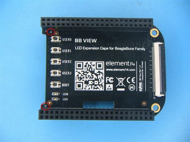
I thought some others might like to know how to get the BB-View working under the latest Debian beta images.


Unfortunately, you are going to have to recompile the Kernel. The video works fine without a recompile (the red/blue swap is easy to fix), but the touchscreen control connections are not the same as the standard TI 4-wire interface. I tried to patch the ti_am335x_tsc.c file, so the changes would be limited to a dts recompile, but I haven't been able to get that working yet (I'm pretty sure it is a state machine / bit assignment issue). But anyway, here are the steps that you need to perform.....


Overview

1) Download the necessary files

     a) Robert Nelson's handy tools for compiling the Beaglebone kernel

     b) BB-View source for Angstrom

2) Build the default kernel

3) Patch the Kernel and perform a fast recompile

4) Copy the new kernel to the Beaglebone

5) Edit the xorg.conf file to correct the Red/Blue color swap

6) Revel in the 4 days you just saved image


Let's Get Started

I am using Ubuntu 12.04 LTS 64 bit running in a VirtualBox VM to compile the kernel:

Make a new folder called bb-view, this is where our build will happen.

> mkdir bb-view

> cd bb-view


Install git, if you haven't already:

> apt-get install git


Clone Robert Nelson's linux-dev project locally. Be prepared for a large download (~100 Mb for the cross-compiler and ~700 Mb for the kernel source).

> git clone https://github.com/RobertCNelson/linux-dev.git


Change into the new linux-dev folder and select branch/tag that matches the Debian version.

> cd linux-dev

> git checkout 3.8.13-bone37 -b tmp


Now we need to build the base image, so our cape drivers folder gets populated. The script will tell you if you need to do or install anything else.

> ./build_kernel.sh


Come back in an hour or so.....(You might want to download the Angstrom source from element14 now)


Patching the Kernel

Extract two files from the Angstrom source:

> unzip angstrom-source.zip

> tar -zxf bb-black-kernel-3.8.13-bb-view.tar.bz2

> cp ./kernel/kernel/drivers/input/touchscreen/ti_am335x_tsc.c  ~/bb-view/linux-dev/KERNEL/drivers/input/touchscreen/

> cp ./kernel/kernel/firmware/capes/BB-VIEW-LCD7-01-00A0.dts  ~/bb-view/linux-dev/KERNEL/firmware/capes/


Now we need to let the compiler know that we want to add the firmware to the build:

> nano   ~/bb-view/linux-dev/KERNEL/firmware/Makefile


Add the following line somewhere near line 192 (CTRL-C will display current cursor position):

BB-VIEW-LCD7-01-00A0.dtbo \


Don't forget the trailing backslash....it is important. Now save and exit by doing CTRL-O, Enter, CTRL-X.

Change back to the linux-dev root folder:

> cd   ~/bb-view/linux-dev


Now issue the kernel rebuild command, this won't take very long at all:

> ./tools/rebuild.sh


Copy Kernel to BBB

The following instructions assume that you already have the Debian beta installed and booted up on the BBB.

The easiest way is to copy the files over the network, via the 'scp' command:

> scp   ~/bb-view/linux-dev/deploy/3.8.13-bone37.zImage   debian@192.168.7.2:/home/debian

Replace debian (both instances) with the username you are running on the BBB and 192.168.7.2 with the IP address of the BBB.


Now log into the BBB and copy the kernel image to the boot partition:

> ssh debian@192.168.7.2

bbb>  sudo cp 3.8.13-bone37.zImage   /boot/uboot/zImage


We need to do one more thing before the LCD will work. Since the cape doesn't have an EEPROM, we need to black-list the HDMI drivers and force-load the BB-VIEW drivers in the boot command file:

bbb>  sudo  nano  /boot/uboot/uEnv.txt


Find the "optargs" line and edit it to be:

optargs=capemgr.disable_partno=BB-BONELT-HDMI,BB-BONELT-HDMIN  capemgr.enable_partno=BB-VIEW-LCD7-01

Notice that the preceding "#" has been removed. You don't want to disable BB-BONE-EMMC-2G, or you won't be able to boot from eMMC.

Now save and exit by doing CTRL-O, Enter, CTRL-X.


Reboot the BBB and the LCD should now work....except the blue and red are reversed.


Fixing Red/Blue Color Swap

This is due to errata in the TI AM335x processor when switching between 16 and 24 bit video modes. To fix this, we must first find the name of our screen:

> ssh debian@192.168.7.2

bbb> cat  /var/log/Xorg.0.log  |  grep  screen

Mine was "Builtin Default fbdev Screen 0"


Now we edit our X configuration file:

bbb> sudo nano  /usr/share/X11/xorg.conf.d/10-evdev.conf


and add a "Screen" section at the end of the file:

Section "Screen"

        Identifier "Builtin Default fbdev Screen 0"

        Monitor "Configured Monitor"

        Device "Configured Video Device"

        DefaultDepth 24

EndSection

Save and exit by doing CTRL-O, Enter, CTRL-X.

Reboot and enjoy!

  • Sign in to reply
  • Cancel

Top Replies

  • Former Member
    Former Member over 11 years ago in reply to Former Member +1
    Hello selsinork, "Which kernel version are you using ?" I use the 3.8. "Did you apply the patch Louis posted ?" I rebuild the kernel with Louis' edits in the "4. Re:[How-to] BB-View on latest Debian" message…
  • Former Member
    Former Member over 11 years ago in reply to Former Member +1
    Ok, so with the overlay loaded then the touch screen driver should be able to work. You can check the proper device using 'evtest' like this: root@lcd:~/evtest# ./evtest No device specified, trying to…
  • Former Member
    Former Member over 11 years ago in reply to Former Member +1
    Interesting. I seem to remember that one of the LEDs on the cape was configured as heartbeat. Perhaps that was the TI-SDK image then as looking at the overlay files I see: gpio-leds-cape-lcd { compatible…
  • Former Member
    Former Member over 11 years ago in reply to Former Member

    You mean on the paper 'Quick Start Guide' where it says "Connect the BB View: Connect the BB View to the BeagleBone or Beaglebone Black using the 46 pin dual-row connectors (J1 and J2)" ?


    J1 & J2 are the two 46pin headers on the cape

    image


    If you've disconnected something else then yes you will likely have a problem.  What problem is hard to tell, maybe the backlight, maybe the touchscreen..  How many connections in the one you removed ?  If it's four then it could be the touchscreen.

    • Cancel
    • Vote Up 0 Vote Down
    • Sign in to reply
    • Cancel
  • Former Member
    Former Member over 11 years ago in reply to Former Member

    No.  Not on the header.  On the 7" LCD.  The ribbon cables for both J1 and J2 are connected via the clamps, to each connector.  When you take it out of the box, the J2 is wrapped around and foam/taped to the underside of the LCD, just on the edge.  I thought the J1 was the same, so, since I'm using J2 and the larger ribbon cable, I pulled (lightly) on the smaller ribbon cable, and it came loose the same way.  Only I double checked with a flashlight, and that smaller ribbon cable does actually have a connector on the underside of the board.  This cable doesn't need to be looped around and remain in the J1 connector does it?  For some sort of continuity?


                      Left connector is J2.  It goes to my BBB

                              |                             Right connector is J1 (not connected)

                              |                                  | 

                             \/                                 \/

          imageimage

                                                    /\

                                                     |

    Underside of 7" LCD display - this is a connector, not just a foam/tape!

    The ribbon cable for J1 was "plugged in", and wrapped around the board

    and connected to J1

    • Cancel
    • Vote Up 0 Vote Down
    • Sign in to reply
    • Cancel
  • Former Member
    Former Member over 11 years ago in reply to Former Member

    Ah.. I have the 4.3" one. Nothing like that on mine.  Someone with a 7" one might be able to help.


    Back of the 4.3" one looks like this

    image

    the white cable to the right goes to the cape.  I take it this is totally different to the back of the 7" one ?

    • Cancel
    • Vote Up 0 Vote Down
    • Sign in to reply
    • Cancel
  • Former Member
    Former Member over 11 years ago in reply to Former Member

    image


    Here's the board.  So I'm on a wild goose chase I think.  The J1 connected ribbon cable should probably have been taken out.

    I'm reflashing my Debian ARM image.  I'm thinking I corrupted the image when I didn't wait until the 4 lights came on.  It seemed like

    a long time (>45 min), and the 4 lights never came on.  But when I restarted on my HDMI, I saw the penguin, so at least part of

    the image was flashed.  It never let me logon though, and the screen went blank, so the disable HDMI is working, but it's not starting up the LCD. I need to be

    able to SSH into the BBB, or otherwise start over I guess.

    • Cancel
    • Vote Up 0 Vote Down
    • Sign in to reply
    • Cancel
  • Former Member
    Former Member over 11 years ago in reply to Former Member

    > 45mins was common with the Angstrom images, but from what I've read it should be approx 15mins with debian.


    if the HDMI disable has worked properly, then in theory you shouldn't see anything on the HDMI output as that driver won't load.  However as the LCD and HDMI framer share the same set of pins I suppose it's possible to have output on both if the timings work out and the monitor, by some miracle, supports the same timings.


    To be sure you properly boot from the uSD to flash, be sure to remove power, hold the boot button, then apply power. The state of the button is only sampled at power-on, not reset, and the sampled state survives a reset, so you keep booting from uSD until you power cycle again.

    • Cancel
    • Vote Up 0 Vote Down
    • Sign in to reply
    • Cancel
  • Former Member
    Former Member over 11 years ago in reply to Former Member

    OK.  New power supply.  I was using one that was older, though the specs were 5A, it seemed the lights were dimmer than using USB power.  This one is w/ the DC connector, and 3.5A 5VDC.  Lights seem brighter now.  Not getting anything on the display, not even a backlight.  Blue lights are blinking, Blue power light is on and bright.  On the cape, I noticed that the Green light is solid, but the red light (LED0) is off now.

    • Cancel
    • Vote Up 0 Vote Down
    • Sign in to reply
    • Cancel
  • Former Member
    Former Member over 11 years ago in reply to Former Member

    Interesting.  I seem to remember that one of the LEDs on the cape was configured as heartbeat.  Perhaps that was the TI-SDK image then as looking at the overlay files I see:


    gpio-leds-cape-lcd {

      compatible = "gpio-leds";

      pinctrl-names = "default";


      pinctrl-0 = <&bb_view_lcd_cape_led_pins>;


      bb_view_led0 {

        label = "bb-view:led0";

        gpios = <&gpio2 28 0>;

        linux,default-trigger = "none";

        default-state = "off";

      };


      bb_view_led1 {

        label = "bb-view:led1";

        gpios = <&gpio1 12 0>;

        linux,default-trigger = "none";

        default-state = "off";

      };

    };


    which implies they should both be off.


    Are you able to ssh into the board, or to use a console cable?

    If you are, you can look see if /sys/class/leds has bb-view:led1 & bb-view:led2 if those dirs exist, you can go into one of them and type "echo heartbeat > trigger" which should result in that led flashing a heartbeat pattern. Should that work the overlay would appear to be loaded ok.

    • Cancel
    • Vote Up +1 Vote Down
    • Sign in to reply
    • Cancel
  • Former Member
    Former Member over 11 years ago in reply to Former Member

    Matthew Trippy wrote:


    OK.  New power supply.  I was using one that was older, though the specs were 5A, it seemed the lights were dimmer than using USB power.  This one is w/ the DC connector, and 3.5A 5VDC.

    As an aside, if your power supply is of the 'USB Charger' type, I'd refer you to the experiences of the Raspberry Pi people who found that the specs on the label on most of them simply can't be trusted...

    A decent PSU is likely to be necessary with the LCD connected as you have and additional thing to power.

    • Cancel
    • Vote Up 0 Vote Down
    • Sign in to reply
    • Cancel
  • Former Member
    Former Member over 11 years ago

    hello , everyone if someone interesting how to  fix colors for 3.8.13, to work without X  , here is the fix:

    replace blue and red color offset values

    compile new kernel and enjoy. (tested on 3.8.13-bone43_1)


    /linux-dev/KERNEL/drivers/gpu/drm/drm_fb_helper.c
    @@ -621,9 +621,9 @@
      var->transp.offset = 15;
      break;
      case 16:
    - var->red.offset = 11;
    + var->blue.offset = 11;
      var->green.offset = 5;
    - var->blue.offset = 0;
    + var->red.offset = 0;
      var->red.length = 5;
      var->green.length = 6;
      var->blue.length = 5;
    @@ -631,9 +631,9 @@
      var->transp.offset = 0;
      break;
      case 24:
    - var->red.offset = 16;
    + var->blue.offset = 16;
      var->green.offset = 8;
    - var->blue.offset = 0;
    + var->red.offset = 0;
      var->red.length = 8;
      var->green.length = 8;
      var->blue.length = 8;
    @@ -641,9 +641,9 @@
      var->transp.offset = 0;
      break;
      case 32:
    - var->red.offset = 16;
    + var->blue.offset = 16;
      var->green.offset = 8;
    - var->blue.offset = 0;
    + var->red.offset = 0;
      var->red.length = 8;
      var->green.length = 8;
      var->blue.length = 8;
    @@ -888,9 +888,9 @@
      info->var.transp.length = 0;
      break;
      case 15:
    - info->var.red.offset = 10;
    + info->var.blue.offset = 10;
      info->var.green.offset = 5;
    - info->var.blue.offset = 0;
    + info->var.red.offset = 0;
      info->var.red.length = 5;
      info->var.green.length = 5;
      info->var.blue.length = 5;
    @@ -898,18 +898,18 @@
      info->var.transp.length = 1;
      break;
      case 16:
    - info->var.red.offset = 11;
    + info->var.blue.offset = 11;
      info->var.green.offset = 5;
    - info->var.blue.offset = 0;
    + info->var.red.offset = 0;
      info->var.red.length = 5;
      info->var.green.length = 6;
      info->var.blue.length = 5;
      info->var.transp.offset = 0;
      break;
      case 24:
    - info->var.red.offset = 16;
    + info->var.blue.offset = 16;
      info->var.green.offset = 8;
    - info->var.blue.offset = 0;
    + info->var.red.offset = 0;
      info->var.red.length = 8;
      info->var.green.length = 8;
      info->var.blue.length = 8;@

    • Cancel
    • Vote Up 0 Vote Down
    • Sign in to reply
    • Cancel
  • compeoree
    compeoree over 11 years ago in reply to Former Member

    @Vagif Thanks for posting this, I was just about to tackle that. I will test out your patch.


    @ Matthew I will look at my 7 inch screen tomorrow and possibly send photos. I have it connected to a BBB, but have not tried to run it on a BBW.


    Louis

    • Cancel
    • Vote Up 0 Vote Down
    • Sign in to reply
    • Cancel
<>
element14 Community

element14 is the first online community specifically for engineers. Connect with your peers and get expert answers to your questions.

  • Members
  • Learn
  • Technologies
  • Challenges & Projects
  • Products
  • Store
  • About Us
  • Feedback & Support
  • FAQs
  • Terms of Use
  • Privacy Policy
  • Legal and Copyright Notices
  • Sitemap
  • Cookies

An Avnet Company © 2025 Premier Farnell Limited. All Rights Reserved.

Premier Farnell Ltd, registered in England and Wales (no 00876412), registered office: Farnell House, Forge Lane, Leeds LS12 2NE.

ICP 备案号 10220084.

Follow element14

  • X
  • Facebook
  • linkedin
  • YouTube