element14 Community
element14 Community
    Register Log In
  • Site
  • Search
  • Log In Register
  • About Us
  • Community Hub
    Community Hub
    • What's New on element14
    • Feedback and Support
    • Benefits of Membership
    • Personal Blogs
    • Members Area
    • Achievement Levels
  • Learn
    Learn
    • Ask an Expert
    • eBooks
    • element14 presents
    • Learning Center
    • Tech Spotlight
    • STEM Academy
    • Webinars, Training and Events
    • Learning Groups
  • Technologies
    Technologies
    • 3D Printing
    • FPGA
    • Industrial Automation
    • Internet of Things
    • Power & Energy
    • Sensors
    • Technology Groups
  • Challenges & Projects
    Challenges & Projects
    • Design Challenges
    • element14 presents Projects
    • Project14
    • Arduino Projects
    • Raspberry Pi Projects
    • Project Groups
  • Products
    Products
    • Arduino
    • Avnet Boards Community
    • Dev Tools
    • Manufacturers
    • Multicomp Pro
    • Product Groups
    • Raspberry Pi
    • RoadTests & Reviews
  • Store
    Store
    • Visit Your Store
    • Choose another store...
      • Europe
      •  Austria (German)
      •  Belgium (Dutch, French)
      •  Bulgaria (Bulgarian)
      •  Czech Republic (Czech)
      •  Denmark (Danish)
      •  Estonia (Estonian)
      •  Finland (Finnish)
      •  France (French)
      •  Germany (German)
      •  Hungary (Hungarian)
      •  Ireland
      •  Israel
      •  Italy (Italian)
      •  Latvia (Latvian)
      •  
      •  Lithuania (Lithuanian)
      •  Netherlands (Dutch)
      •  Norway (Norwegian)
      •  Poland (Polish)
      •  Portugal (Portuguese)
      •  Romania (Romanian)
      •  Russia (Russian)
      •  Slovakia (Slovak)
      •  Slovenia (Slovenian)
      •  Spain (Spanish)
      •  Sweden (Swedish)
      •  Switzerland(German, French)
      •  Turkey (Turkish)
      •  United Kingdom
      • Asia Pacific
      •  Australia
      •  China
      •  Hong Kong
      •  India
      •  Korea (Korean)
      •  Malaysia
      •  New Zealand
      •  Philippines
      •  Singapore
      •  Taiwan
      •  Thailand (Thai)
      • Americas
      •  Brazil (Portuguese)
      •  Canada
      •  Mexico (Spanish)
      •  United States
      Can't find the country/region you're looking for? Visit our export site or find a local distributor.
  • Translate
  • Profile
  • Settings
Single-Board Computers
  • Products
  • Dev Tools
  • Single-Board Computers
  • More
  • Cancel
Single-Board Computers
Forum Omega2 as Irrigation Controller with only 3 GPIO
  • Blog
  • Forum
  • Documents
  • Files
  • Members
  • Mentions
  • Sub-Groups
  • Tags
  • More
  • Cancel
  • New
Join Single-Board Computers to participate - click to join for free!
Actions
  • Share
  • More
  • Cancel
Forum Thread Details
  • State Suggested Answer
  • Replies 1 reply
  • Answers 1 answer
  • Subscribers 55 subscribers
  • Views 551 views
  • Users 0 members are here
  • omega2
  • gpio
  • 74138
Related

Omega2 as Irrigation Controller with only 3 GPIO

TCPMeta
TCPMeta over 5 years ago

I had bought a couple of Omega2 boards a while back and I thought I would use one for this project.

The scope of the project was to use the GPIO to drive four Relays since it is a four Zone sprinkler System. Have Crontab pull the GPIO HIGH/LOW at a given time to drive the Relays to water the Lawn.


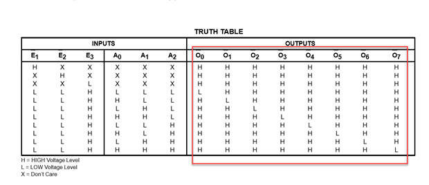
I found out there are only three GPIO pins that can really be controlled. All of the others are tied to the CPU and such. I need four GPIO to drive the Relays as planned. However going through a Data Book for an idea on driving one or three GPIO pins to control four Outputs. I came across the 74138 that is a 3-line to 8-line Demultiplexer. However it is Active HIGH on the Outputs and pulls an Output LOW. I would think a Hex Inverter would work to "Flip the Bits" but the question is should I put the Hex Inverter on the Input of the 74138 or on the Output and tweak the Software to put the GPIO LOW to make the Output HIGH?

  • Sign in to reply
  • Cancel

Top Replies

  • shabaz
    shabaz over 5 years ago +1 suggested
    Hi Leland, If you want only one output high at a time, then the inverters have to be on the output of the '138, not on the input, because there's no entry in the truth table that can allow it based on…
  • shabaz
    0 shabaz over 5 years ago

    Hi Leland,


    If you want only one output high at a time, then the inverters have to be on the output of the '138, not on the input, because there's no entry in the truth table that can allow it based on any input inversion. The red highlighted area shows all rows have more than one output high in the truth table in the '138 data sheet:

    image

    A '138 and inverter based solution means only one output can be turned on at a time, which might suit your immediate needs, but isn't very general-purpose for reuse in other projects. There are some other simpler ways. First, it is worth confirming that there really are only three pins available. If your project will never need more than 4 GPIO, then this should be easily possible with the Omega2 board according to the datasheet it has 18 I/O. But maybe you are using the remainder I/O or don't have access via some other board.


    As another idea, a more general-purpose solution is to use an I/O expanderI/O expander. It costs a bit more but it is still sub-$1. According to the Omega2 website, there is a relay board which by coincidence uses the same I/O expander IC. This means you've now potentially got the benefit of their ready-made relay control code if you use the same chip, and probably any tutorials people may have written with the Omega2 board and their relay board can be followed, such as this one: https://docs.onion.io/omega2-docs/using-relay-expansion.html

    Here's what the circuit could look like (the INT pin can be left unused) - the I/O expander datasheet has more information, or if you google that part number, there's dozens of projects/tutorials using it due to the popularity:

    image


    With such a solution you've got 8 potential relay outputs, or you can use them for other purposes (as inputs, or for flashing LEDs etc), and you can reuse the same circuit for other projects, without running out of GPIO pins or needing inverter chips.

    • Cancel
    • Vote Up +1 Vote Down
    • Sign in to reply
    • Verify Answer
    • Reject Answer
    • Cancel
element14 Community

element14 is the first online community specifically for engineers. Connect with your peers and get expert answers to your questions.

  • Members
  • Learn
  • Technologies
  • Challenges & Projects
  • Products
  • Store
  • About Us
  • Feedback & Support
  • FAQs
  • Terms of Use
  • Privacy Policy
  • Legal and Copyright Notices
  • Sitemap
  • Cookies

An Avnet Company © 2025 Premier Farnell Limited. All Rights Reserved.

Premier Farnell Ltd, registered in England and Wales (no 00876412), registered office: Farnell House, Forge Lane, Leeds LS12 2NE.

ICP 备案号 10220084.

Follow element14

  • X
  • Facebook
  • linkedin
  • YouTube