element14 Community
element14 Community
    Register Log In
  • Site
  • Search
  • Log In Register
  • About Us
  • Community Hub
    Community Hub
    • What's New on element14
    • Feedback and Support
    • Benefits of Membership
    • Personal Blogs
    • Members Area
    • Achievement Levels
  • Learn
    Learn
    • Ask an Expert
    • eBooks
    • element14 presents
    • Learning Center
    • Tech Spotlight
    • STEM Academy
    • Webinars, Training and Events
    • Learning Groups
  • Technologies
    Technologies
    • 3D Printing
    • FPGA
    • Industrial Automation
    • Internet of Things
    • Power & Energy
    • Sensors
    • Technology Groups
  • Challenges & Projects
    Challenges & Projects
    • Design Challenges
    • element14 presents Projects
    • Project14
    • Arduino Projects
    • Raspberry Pi Projects
    • Project Groups
  • Products
    Products
    • Arduino
    • Avnet Boards Community
    • Dev Tools
    • Manufacturers
    • Multicomp Pro
    • Product Groups
    • Raspberry Pi
    • RoadTests & Reviews
  • Store
    Store
    • Visit Your Store
    • Choose another store...
      • Europe
      •  Austria (German)
      •  Belgium (Dutch, French)
      •  Bulgaria (Bulgarian)
      •  Czech Republic (Czech)
      •  Denmark (Danish)
      •  Estonia (Estonian)
      •  Finland (Finnish)
      •  France (French)
      •  Germany (German)
      •  Hungary (Hungarian)
      •  Ireland
      •  Israel
      •  Italy (Italian)
      •  Latvia (Latvian)
      •  
      •  Lithuania (Lithuanian)
      •  Netherlands (Dutch)
      •  Norway (Norwegian)
      •  Poland (Polish)
      •  Portugal (Portuguese)
      •  Romania (Romanian)
      •  Russia (Russian)
      •  Slovakia (Slovak)
      •  Slovenia (Slovenian)
      •  Spain (Spanish)
      •  Sweden (Swedish)
      •  Switzerland(German, French)
      •  Turkey (Turkish)
      •  United Kingdom
      • Asia Pacific
      •  Australia
      •  China
      •  Hong Kong
      •  India
      •  Korea (Korean)
      •  Malaysia
      •  New Zealand
      •  Philippines
      •  Singapore
      •  Taiwan
      •  Thailand (Thai)
      • Americas
      •  Brazil (Portuguese)
      •  Canada
      •  Mexico (Spanish)
      •  United States
      Can't find the country/region you're looking for? Visit our export site or find a local distributor.
  • Translate
  • Profile
  • Settings
BeagleBoard
  • Products
  • Dev Tools
  • Single-Board Computers
  • BeagleBoard
  • More
  • Cancel
BeagleBoard
Blog BBB - Small OLED Graphic Display
  • Blog
  • Forum
  • Documents
  • Quiz
  • Polls
  • Files
  • Members
  • Mentions
  • Sub-Groups
  • Tags
  • More
  • Cancel
  • New
Join BeagleBoard to participate - click to join for free!
  • Share
  • More
  • Cancel
Group Actions
  • Group RSS
  • More
  • Cancel
Engagement
  • Author Author: shabaz
  • Date Created: 4 Jan 2014 1:31 AM Date Created
  • Views 5945 views
  • Likes 2 likes
  • Comments 37 comments
  • oled
  • lcd
  • beagleboneblack
  • small_oled_displays
  • bbb
  • texas_instruments
  • beagle_bone_black
  • oled_displays
  • ti
Related
Recommended

BBB - Small OLED Graphic Display

shabaz
shabaz
4 Jan 2014

Introduction

There are many compact LCD and OLED displays available, but the documentation tends to be poor. This is just a quick post to record a working configuration (circuit and code) to get a compact OLED display working. A 160x128 OLED display was selected, model DD-160128FC-1A (Farnell code 1498857, also available from Newark). It is a very high quality display.

image

The display is an Organic LED (OLED) type. For interfacing a similar-sized LCD display, see here.

The code that was written is targetted for the BeagleBone Black (BBB) but can be very easily adapted for any platform. For the BBB, it uses an I/O library called iolib (see here for more details) intended for quickly prototyping a solution. The library code is already included in the zip file attached to this post.


The code is prototype level – ideally it would be rewritten to use faster interfaces (e.g. SPI, or PRU processor), but it runs fast enough for many use-cases - with the current code the display update rate is more than sufficient for text information and simple diagrams. Perhaps 30 updates per second are possible with the current code if the entire screen is not being refreshed.


The code has a few graphic commands but not much – it is an easy matter to use one of the many existing third party graphics libraries if anything beyond simple text/graphics is required.

The current code has just these capabilities:

  • Point plotting
  • Line plotting
  • Rectangles (filled, unfilled, bordered)
  • Scalable Text
  • Graphic image read from raw file into RAM
  • Graphic image display from RAM


Display Dimensions and Notes

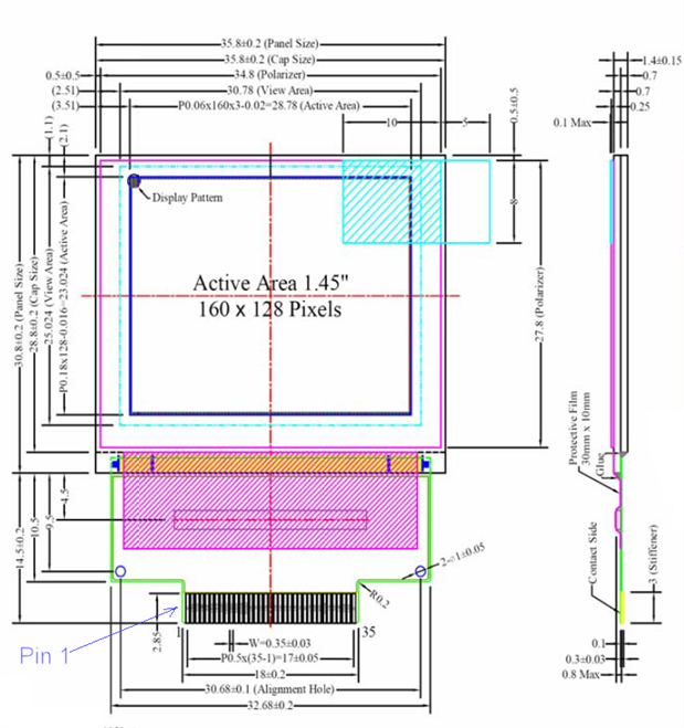
The display has a Densitron code DD-160128FC-1A. The screen has the label “UG-6028GDEAF01” on the rear. A connector by Omron (Omron code XF2M35151A  Farnell code 1112561) should fit.

Shown below is a diagram from the datasheet. The screen is very thin (about 1.5mm). There is an in-built controller (Syncoam SEPS525) located in the hatched purple area. The display is organized such that memory address 0 is top-left (where the round blob is shown) like most displays. Personally I prefer to have the origin at bottom-left, so the code uses that reference point as (0,0) instead of top-left.

image


Example Images

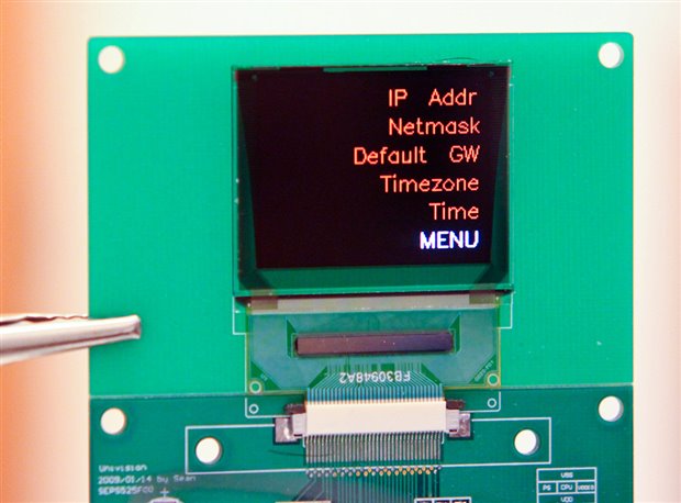
These photos were taken in a brightly lit room. The screen appears bright, sharp and has a more rich/saturated quality than LCD displays:

image


This animated character is drawn at position (0,0), since co-ordinates are taken from bottom-left in the attached code:

image


An example menu. A circuit board could have buttons to the side:

image


Video

Note - The photographs are more representative of what the display looks like in action. The image quality appears extremely bright and sharp when viewed in person – about the same as a mobile phone

The video clip here is only really useful to show the update speeds for the current code. The pulsing/flickering and horizontal banding visible in the video is not apparent in real life.

Click here for the video- having real trouble with it, it is from a camera I don't normally use and the quality is pretty bad - sorry. The final animation is actually quite smooth in real life.


Circuit

There is an optional demo board available, but it is quite basic; it has no active components, it is almost just a breakout board. The demo board was intended to speed development up, but the datasheet slowed things right back down again - the datasheet from Densitron is poor and has many errors (they have taken absolutely no care to review it).

This is the required circuit to get the display working in a serial mode:

image


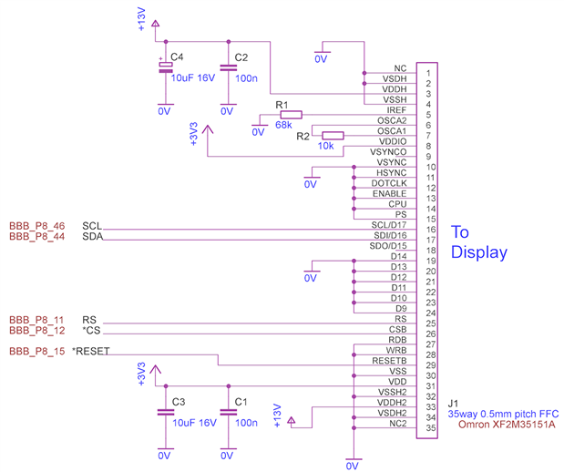
An appropriate connector shown here (Farnell code 1112561) should be compatible (35 way, 0.5mm pitch) but was not tested.


The display requires a low voltage supply (3.3V max) which matches what the BBB offers. A higher voltage (13V) supply is also required. I didn’t have any appropriate IC over the holiday period, so a Maxim MAX734 was used, with some resistors used to adjust the voltage to 13V. This is not recommended since it is outside the specification of the MAX734, but the circuit is shown below since it worked for the prototype. It is recommended to use a different circuit.

image

Once assembled, the circuit was connected to the BBB as indicated in the schematic. The 0V, +3.3V and +5V supply rails were powered directly from the BeagleBone, using the BBB header P9 pins 1, 3 and 5 respectively.


Software

The code is attached to this post. It is written in C. Refer to the file ‘oled.c’ to see the functions available. The main function currently also resides in that file. It runs five demonstrations when executed.


To use it, create a folder off the home directory (/home/root in my case):

mkdir –p development/oled
cd development/oled

The path will now be /home/root/development/oled

Copy the files into this location, then type the following to compile the code:

make install

The demo can now be run by typing:

./oled


Summary

It would be worthwhile creating a board for this display, and using it for small projects with the BBB where a high quality image is needed. A good amount of information can be represented on this display. It is easy to use with the example C code library, but will require a 13V supply (a small circuit can be used to generate this from the BBB’s 5V supply rail).

For larger displays, the 4.3” and 7” BB-View displays are available.


The revision 1 code is attached below for reference, but is also available here so that changes can be tracked.

Attachments:
oled-SEPS525-rev1.zip
  • Sign in to reply

Top Comments

  • Kilohercas
    Kilohercas over 11 years ago +1
    I have all code for htc desire AMOLED screen. If you want try to connect to LCDC at 800x480 resolution, that would be greait
  • Kilohercas
    Kilohercas over 11 years ago in reply to shabaz +1
    you can get from ebay, cost only 20$. For HTC Desire A8181 G7 LCD Display Screen Samsung AMOLED Repalcement | eBay but you will need pair of connectors from mouser.com, since i was unable to find exact…
  • DAB
    DAB over 11 years ago +1
    Good post, I especially like your sharing the pinouts and interface issues. DAB
  • shabaz
    shabaz over 10 years ago in reply to Former Member

    Hi Mohit,


    800mA is a huge amount (>20 times expected) so it could have caused a permanent fault.

    The datasheet does mention that there is a power supply sequence, and the 13V supply should not be switched on unless the 3.3V supply

    is already present. As you say, probably even +5V should not be present on that pin until the 3.3V is supplied.

    There are not many DC-DC converters will full shutdown capability, so probably the best way is to use a MOSFET to switch the power on that pin.

    Apologies that was not clear in the post, although I did make it clear that the 13V supply needed complete rework since I just used whatever was

    at hand (it was at Christmas time 18 months ago : ( and no chance to order any bits : ( and the shutdown signal I used would not have

    removed the 5V supply minus the diode drop. It was an oversight on my part.

    But definitely 13V should not be enabled before the 3.3V supply.


    I still have my display and do intend to still use it, and will be revisiting the 13V driver portion at some stage. But if you get there before me,

    please do share your circuit.


    Also, for future, definitely set a current limit on your power supply before switching on such circuits. This is all experimental prototype stuff (and OLED

    display datasheets are generally poor) so best to take some precautions during prototyping.


    Thanks.

    • Cancel
    • Vote Up 0 Vote Down
    • Sign in to reply
    • More
    • Cancel
  • Former Member
    Former Member over 10 years ago

    Hi Shabaz,


    I judiciously tried to follow the hardware configuration showed by you with +13V coming from LM27313 but somewhere things got wrong:-image


    Firstly I made the interface exactly as you had shown but tried to test the OLED separately without connecting to the BBB. In doing so we gave only +13V and did not provide +3.3V. We saw huge current of around 800mA flowing from the power supply. I do not know whether it damaged my OLED as I did not see any smoke and I even switched the supply off in say around 10seconds or so.


    There after assuming that everything is fine, I took the C code written by you and wrote it in my way as I wanted BBB to interface with it using bare metal programming. I have attached the code herewith. Here I have used LCD_DATA10 as RESET, LCD_DATA9 as HV_EN, LCD_DATA7 - CS_B, LCD_DATA5 - RS, LCD_DATA3 - SDO and LCD_DATA1 - SCL. I now connected BBB with my cape which has oled connector driven by +13V and +3.3V both generated using my on cape regulators.


    After executing the code upto display_on_off command = 1 and just before demo codes, I find that the OLED screen is completely dead. Why is it so? When should anything appear on the OLED  at all. I have never used OLED before or is it that my OLED is gone bad?


    Further there is one more hardware doubt I have that even during HV supply is disabled through shutdown logic, still +5V supply will go to VDDH and exactly that power ramp does not start from 0V. Does this cause any problem?


    Will be very helpful if you could reply on this as I had a lot of assurances on this post based on which I started my development but I feel lost somewhere. I even attach the schema of my cape herewith.


    Here is my code :-


    /**

    * \file   gpioLEDBlink.c

    *

    *  \brief  This application uses a GPIO pin to blink the LED.

    *

    *          Application Configurations:

    *

    *              Modules Used:

    *                  GPIO1

    *

    *              Configuration Parameters:

    *                  None

    *

    *          Application Use Case:

    *              1) The GPIO pin GPIO1[23] is used as an output pin.

    *              2) This pin is alternately driven HIGH and LOW. A finite delay

    *                 is given to retain the pin in its current state.

    *

    *          Running the example:

    *              On running the example, the LED on beaglebone would be seen

    *              turning ON and OFF alternatively.

    *

    */


    /*

    * Copyright (C) 2010 Texas Instruments Incorporated - http://www.ti.com/

    */

    /*

    *  Redistribution and use in source and binary forms, with or without

    *  modification, are permitted provided that the following conditions

    *  are met:

    *

    *    Redistributions of source code must retain the above copyright

    *    notice, this list of conditions and the following disclaimer.

    *

    *    Redistributions in binary form must reproduce the above copyright

    *    notice, this list of conditions and the following disclaimer in the

    *    documentation and/or other materials provided with the  

    *    distribution.

    *

    *    Neither the name of Texas Instruments Incorporated nor the names of

    *    its contributors may be used to endorse or promote products derived

    *    from this software without specific prior written permission.

    *

    *  THIS SOFTWARE IS PROVIDED BY THE COPYRIGHT HOLDERS AND CONTRIBUTORS

    *  "AS IS" AND ANY EXPRESS OR IMPLIED WARRANTIES, INCLUDING, BUT NOT

    *  LIMITED TO, THE IMPLIED WARRANTIES OF MERCHANTABILITY AND FITNESS FOR

    *  A PARTICULAR PURPOSE ARE DISCLAIMED. IN NO EVENT SHALL THE COPYRIGHT

    *  OWNER OR CONTRIBUTORS BE LIABLE FOR ANY DIRECT, INDIRECT, INCIDENTAL,

    *  SPECIAL, EXEMPLARY, OR CONSEQUENTIAL DAMAGES (INCLUDING, BUT NOT

    *  LIMITED TO, PROCUREMENT OF SUBSTITUTE GOODS OR SERVICES; LOSS OF USE,

    *  DATA, OR PROFITS; OR BUSINESS INTERRUPTION) HOWEVER CAUSED AND ON ANY

    *  THEORY OF LIABILITY, WHETHER IN CONTRACT, STRICT LIABILITY, OR TORT

    *  (INCLUDING NEGLIGENCE OR OTHERWISE) ARISING IN ANY WAY OUT OF THE USE

    *  OF THIS SOFTWARE, EVEN IF ADVISED OF THE POSSIBILITY OF SUCH DAMAGE.

    *

    */


    #include "soc_AM335x.h"

    #include "beaglebone.h"

    #include "gpio_v2.h"


    // Added by Mohit Hada on 05/08/2015 for testing OLED

    #include "hw_control_AM335x.h"

    #include "hw_cm_wkup.h"

    #include "hw_cm_per.h"

    #include "hw_types.h"


    /*****************************************************************************

    **                INTERNAL MACRO DEFINITIONS

    *****************************************************************************/

    // #define GPIO_INSTANCE_ADDRESS           (SOC_GPIO_1_REGS) modified by Mohit Hada on 05/08/2015

    #define GPIO_INSTANCE_ADDRESS           (SOC_GPIO_2_REGS) // modified by Mohit Hada on 05/08/2015 ofr testing of OLED

    #define GPIO_INSTANCE_PIN_NUMBER        (23)


    /// Introduced by Mohit Hada on 05/08/2015

    #define OSC_CTL                          0x02

    #define IREF                             0x80

    #define CLOCK_DIV                        0x03

    #define REDUCE_CURRENT                   0x04

    #define SOFT_RST                         0x05

    #define DISP_ON_OFF                      0x06

    #define PRECHARGE_TIME_R                 0x08

    #define PRECHARGE_TIME_G                 0x09

    #define PRECHARGE_TIME_B                 0x0A

    #define PRECHARGE_CURRENT_R              0x0B

    #define PRECHARGE_CURRENT_G              0x0C

    #define PRECHARGE_CURRENT_B              0x0D

    #define DRIVING_CURRENT_R                0x10

    #define DRIVING_CURRENT_G                0x11

    #define DRIVING_CURRENT_B                0x12

    #define DISPLAY_MODE_SET                 0x13

    #define RGB_IF                           0x14

    #define RGB_POL                          0x15

    #define MEMORY_WRITE_MODE                0x16

    #define MX1_ADDR                         0x17

    #define MX2_ADDR                         0x18

    #define MY1_ADDR                         0x19

    #define MY2_ADDR                         0x1A

    #define MEM_PTR_X                        0x20

    #define MEM_PTR_Y                        0x21

    #define DDRAM_DATA_ACCESS_PORT           0x22

    #define GRAY_SCALE_TABLE_INDEX           0x50

    #define GRAY_SCALE_TABLE_DATA            0x51

    #define DUTY                             0x28

    #define DSL                              0x29

    #define D1_DDRAM_FAC                     0x2E

    #define D1_DDRAM_FAR                     0x2F

    #define D2_DDRAM_SAC                     0x31

    #define D2_DDRAM_SAR                     0x32

    #define SCR1_FX1                         0x33

    #define SCR1_FX2                         0x34

    #define SCR1_FY1                         0x35

    #define SCR1_FY2                         0x36

    #define SCR2_SX1                         0x37

    #define SCR2_SX2                         0x38

    #define SCR2_SY1                         0x39

    #define SCR2_SY2                         0x3A

    #define SCREEN_SAVER_CONTROL             0x3B

    #define SS_SLEEP_TIMER                   0x3C

    #define SCREEN_SAVER_MODE                0x3D

    #define SS_SCR1_FU                       0x3E

    #define SS_SCR1_MXY                      0x3F

    #define SS_SCR2_FU                       0x40

    #define SS_SCR2_MXY                      0x41

    #define MOVING_DIRECTION                 0x42

    #define SS_SCR2_SX1                      0x47

    #define SS_SCR2_SX2                      0x48

    #define SS_SCR2_SY1                      0x49

    #define SS_SCR2_SY2                      0x4A

    #define FIN                              0xFF

    /////////////////////////////////////////////////////////////////////////////


    /*****************************************************************************

    **                INTERNAL FUNCTION PROTOTYPES

    *****************************************************************************/

    static void Delay(unsigned int count);

    void GPIO2ModuleClkConfig(void);

    void GPIO2PinMuxSetup(void);

    void oled_powerup(void);

    void write_param(unsigned char addr, unsigned char val);

    void write_idx(unsigned char v);

    void write_ctrl(unsigned char v);

    void rect_fill(unsigned char x, unsigned char y, unsigned char dx, unsigned char dy,

                 unsigned int lcol, unsigned int fcol);

    void write_16(unsigned short int v);


    /******************************************************************************

    **                      TYPE DEF DEFINED FOR OLED   by MOHIT HADA on 05/08/2015 for testing OLED

    ******************************************************************************/

    typedef struct av_s

    {

        unsigned char addr;

        unsigned char val;

    } av_t;


    /********************************************************************************

    ** GLOBAL VARIABLES

    ********************************************************************************/


    const av_t oled_init_arr[]=

    {

        {DISP_ON_OFF,0},

        {OSC_CTL,1},

        {CLOCK_DIV, 0x30},

        {REDUCE_CURRENT, 0},

        {IREF, 0},

        {PRECHARGE_TIME_R, 1},

        {PRECHARGE_TIME_G, 1},

        {PRECHARGE_TIME_B, 1},

        {PRECHARGE_CURRENT_R, 0x0c},

        {PRECHARGE_CURRENT_G, 0x19},

        {PRECHARGE_CURRENT_B, 0x15},

        {DRIVING_CURRENT_R, 0x32},

        {DRIVING_CURRENT_G, 0x27},

        {DRIVING_CURRENT_B, 0x2b},

        {DISPLAY_MODE_SET, 0},

        {RGB_IF, 0x11},

        {RGB_POL,0},

        {MEMORY_WRITE_MODE, 0x26}, /*76*/ // TODO: We need to check as to whether this is correct or not

        {MX1_ADDR, 0},

        {MX2_ADDR, 0x9f},

        {MY1_ADDR, 0},

        {MY2_ADDR, 0x7f},

        {MEM_PTR_X, 0},

        {MEM_PTR_Y, 0},

        {DUTY, 0x7f},

        {DSL, 0},

        {D1_DDRAM_FAC, 0},

        {D1_DDRAM_FAR, 0},

        {D2_DDRAM_SAC, 0},

        {D2_DDRAM_SAR, 0},

        {SCR1_FX1, 0},

        {SCR1_FX2, 0x9f},

        {SCR1_FY1, 0},

        {SCR1_FY2, 0x7f},

        {FIN, FIN}

    };


    /*****************************************************************************

    **                INTERNAL FUNCTION DEFINITIONS

    *****************************************************************************/

    /*

    ** The main function. Application starts here.

    */

    int main()

    {

    //    /* Enabling functional clocks for GPIO1 instance. */

    //    GPIO1ModuleClkConfig();

    //

    //    /* Selecting GPIO1[23] pin for use. */

    //    GPIO1Pin23PinMuxSetup();

    //

    //    /* Enabling the GPIO module. */

    //    GPIOModuleEnable(GPIO_INSTANCE_ADDRESS);

    //

    //    /* Resetting the GPIO module. */

    //    GPIOModuleReset(GPIO_INSTANCE_ADDRESS);

    //

    //    /* Setting the GPIO pin as an output pin. */

    //    GPIODirModeSet(GPIO_INSTANCE_ADDRESS,

    //                   GPIO_INSTANCE_PIN_NUMBER,

    //                   GPIO_DIR_OUTPUT);

    //    while(1)

    //    {

    //        /* Driving a logic HIGH on the GPIO pin. */

    //        GPIOPinWrite(GPIO_INSTANCE_ADDRESS,

    //                     GPIO_INSTANCE_PIN_NUMBER,

    //                     GPIO_PIN_HIGH);

    //

    //        Delay(0x3FFFF);

    //

    //        /* Driving a logic LOW on the GPIO pin. */

    //        GPIOPinWrite(GPIO_INSTANCE_ADDRESS,

    //                     GPIO_INSTANCE_PIN_NUMBER,

    //                     GPIO_PIN_LOW);

    //

    //        Delay(0x3FFFF);

    //    }


    //  LCD_DATA10 on BBB  - GPIO2 - 16 - TO BE USED AS RESET

    //    LCD_DATA9  on BBB  - GPIO2 - 15 - TO BE USED HV_EN

    //     LCD_DATA7  on BBB  - GPIO2 - 13 - TO BE USED CS_B

    //  LCD_DATA5  on BBB  - GPIO2 - 11 - TO BE USED RS

    //  LCD_DATA3  on BBB  - GPIO2 - 9  - TO BE USED SDO

    //  LCD_DATA1  on BBB  - GPIO2 - 7  - TO BE USED SCL


            /* Enabling functional clocks for GPIO1 instance. */

            GPIO2ModuleClkConfig();


            /* Selecting GPIO2[16,15,13,11,9 and 7] pin for use. */

            GPIO2PinMuxSetup();   // to be checked...


            /* Enabling the GPIO module. */

            GPIOModuleEnable(GPIO_INSTANCE_ADDRESS);


            /* Resetting the GPIO module. */

            GPIOModuleReset(GPIO_INSTANCE_ADDRESS);


            /* Setting the GPIO2 PIN -16  pin as an output pin. */

            GPIODirModeSet(GPIO_INSTANCE_ADDRESS,

                           16,

                           GPIO_DIR_OUTPUT);

            /* Setting the GPIO2 PIN -15  pin as an output pin. */

            GPIODirModeSet(GPIO_INSTANCE_ADDRESS,

                           15,

                           GPIO_DIR_OUTPUT);

            /* Setting the GPIO2 PIN -13  pin as an output pin. */

            GPIODirModeSet(GPIO_INSTANCE_ADDRESS,

                           13,

                           GPIO_DIR_OUTPUT);

            /* Setting the GPIO2 PIN -11  pin as an output pin. */

            GPIODirModeSet(GPIO_INSTANCE_ADDRESS,

                           11,

                           GPIO_DIR_OUTPUT);

            /* Setting the GPIO2 PIN -9  pin as an output pin. */

            GPIODirModeSet(GPIO_INSTANCE_ADDRESS,

                           9,

                           GPIO_DIR_OUTPUT);

            /* Setting the GPIO2 PIN -7  pin as an output pin. */

            GPIODirModeSet(GPIO_INSTANCE_ADDRESS,

                           7,

                           GPIO_DIR_OUTPUT);


    //******************Initial State of OLED Pins***********************////


            /* PUT OLED IN RESET STATE */

            GPIOPinWrite(GPIO_INSTANCE_ADDRESS,

                         16,

                         GPIO_PIN_LOW);

            /* DISABLE HV. */

            GPIOPinWrite(GPIO_INSTANCE_ADDRESS,

                         15,

                         GPIO_PIN_LOW);

            /* Driving a logic HIGH on the CS pin. */

            GPIOPinWrite(GPIO_INSTANCE_ADDRESS,

                         13,

                         GPIO_PIN_HIGH);

            /* Driving a logic HIGH on the RS pin. */

            GPIOPinWrite(GPIO_INSTANCE_ADDRESS,

                         11,

                         GPIO_PIN_HIGH);

            /* Driving a logic HIGH on the SDO pin. */

            GPIOPinWrite(GPIO_INSTANCE_ADDRESS,

                         9,

                         GPIO_PIN_LOW);

            /* Driving a logic HIGH on the SCL pin. */

            GPIOPinWrite(GPIO_INSTANCE_ADDRESS,

                         7,

                         GPIO_PIN_LOW);


            Delay(0x3FFFF);


            /* PUT OLED OUT OF RESET STATE */

             GPIOPinWrite(GPIO_INSTANCE_ADDRESS,

                          16,

                          GPIO_PIN_HIGH);


             oled_powerup(); // configures the OLED, and powers it up


    }


    /*

    ** A function which is used to generate a delay.

    */

    static void Delay(volatile unsigned int count)

    {

        while(count--);

    }


    void GPIO2ModuleClkConfig(void)

    {


        /* Writing to MODULEMODE field of CM_PER_GPIO2_CLKCTRL register. */

        HWREG(SOC_CM_PER_REGS + CM_PER_GPIO2_CLKCTRL) |=

              CM_PER_GPIO2_CLKCTRL_MODULEMODE_ENABLE;


        /* Waiting for MODULEMODE field to reflect the written value. */

        while(CM_PER_GPIO2_CLKCTRL_MODULEMODE_ENABLE !=

              (HWREG(SOC_CM_PER_REGS + CM_PER_GPIO2_CLKCTRL) &

               CM_PER_GPIO2_CLKCTRL_MODULEMODE));

        /*

        ** Writing to OPTFCLKEN_GPIO_2_GDBCLK bit in CM_PER_GPIO2_CLKCTRL

        ** register.

        */

        HWREG(SOC_CM_PER_REGS + CM_PER_GPIO2_CLKCTRL) |=

              CM_PER_GPIO2_CLKCTRL_OPTFCLKEN_GPIO_2_GDBCLK;


        /*

        ** Waiting for OPTFCLKEN_GPIO_2_GDBCLK bit to reflect the desired

        ** value.

        */

        while(CM_PER_GPIO2_CLKCTRL_OPTFCLKEN_GPIO_2_GDBCLK !=

              (HWREG(SOC_CM_PER_REGS + CM_PER_GPIO2_CLKCTRL) &

               CM_PER_GPIO2_CLKCTRL_OPTFCLKEN_GPIO_2_GDBCLK));


        /*

        ** Waiting for IDLEST field in CM_PER_GPIO2_CLKCTRL register to attain the

        ** desired value.

        */

        while((CM_PER_GPIO2_CLKCTRL_IDLEST_FUNC <<

               CM_PER_GPIO2_CLKCTRL_IDLEST_SHIFT) !=

               (HWREG(SOC_CM_PER_REGS + CM_PER_GPIO2_CLKCTRL) &

                CM_PER_GPIO2_CLKCTRL_IDLEST));


        /*

        ** Waiting for CLKACTIVITY_GPIO_2_GDBCLK bit in CM_PER_L4LS_CLKSTCTRL

        ** register to attain desired value.

        */

        while(CM_PER_L4LS_CLKSTCTRL_CLKACTIVITY_GPIO_2_GDBCLK !=

              (HWREG(SOC_CM_PER_REGS + CM_PER_L4LS_CLKSTCTRL) &

               CM_PER_L4LS_CLKSTCTRL_CLKACTIVITY_GPIO_2_GDBCLK));

    }


    void GPIO2PinMuxSetup(void)

    {

        HWREG(SOC_CONTROL_REGS + CONTROL_CONF_LCD_DATA(10)) = CONTROL_CONF_MUXMODE(7);

        HWREG(SOC_CONTROL_REGS + CONTROL_CONF_LCD_DATA(9))  = CONTROL_CONF_MUXMODE(7);

        HWREG(SOC_CONTROL_REGS + CONTROL_CONF_LCD_DATA(7))  = CONTROL_CONF_MUXMODE(7);

        HWREG(SOC_CONTROL_REGS + CONTROL_CONF_LCD_DATA(5))  = CONTROL_CONF_MUXMODE(7);

        HWREG(SOC_CONTROL_REGS + CONTROL_CONF_LCD_DATA(3))  = CONTROL_CONF_MUXMODE(7);

        HWREG(SOC_CONTROL_REGS + CONTROL_CONF_LCD_DATA(1))  = CONTROL_CONF_MUXMODE(7);


    }


    // This configures the display, applies the high voltage and enables the display

    void oled_powerup(void)

    {

        int i=0;

        int not_finished=1;

        unsigned char addr, val;

        while(not_finished)

        {

            addr=oled_init_arr[i].addr;

            val=oled_init_arr[i].val;

            if ((addr==FIN) && (val==FIN))

            {

                not_finished=0;

                break;

            }

            write_param(addr, val);

            i++;

        }


        /* ENABLE HV. */

        GPIOPinWrite(GPIO_INSTANCE_ADDRESS,

                     15,

                     GPIO_PIN_HIGH);


        Delay(0x3FFFF);


        rect_fill(0, 0, 160, 128, 0x0000, 0x0000); // clear to blank screen


        write_param(DISP_ON_OFF, 1);


        Delay(0x0FFFF);


    }


    // Use this to write an instruction to the display

    void write_param(unsigned char addr, unsigned char val)

    {

        //if (display_dbg) printf("addr=0x%02x, val=0x%02x\n", addr, val);

        write_idx(addr);

        write_ctrl(val);

    }


    void write_idx(unsigned char v)

    {

        int i;

        unsigned char ibyte;

    //    RS_LOW;

    //    CS_LOW;

    //    SCL_LOW;


       /* RS LOW FOR COMMAND TRANSFER */

        GPIOPinWrite(GPIO_INSTANCE_ADDRESS,

                     11,

                     GPIO_PIN_LOW);

        /* CS LOW FOR SPI INTERFACE */

        GPIOPinWrite(GPIO_INSTANCE_ADDRESS,

                     13,

                     GPIO_PIN_LOW);

        /* Driving a logic LOW on the SCL pin. */

        GPIOPinWrite(GPIO_INSTANCE_ADDRESS,

                     7,

                     GPIO_PIN_LOW);


        ibyte=v;

        // transmit instruction byte

        for (i=0; i<8; i++)

        {

            if (ibyte & 0x80) // If MSB of data is '1' // TODO: we need to check whether such comparison can be done or not

            {

                //SDO HIGH

                GPIOPinWrite(GPIO_INSTANCE_ADDRESS,

                             9,

                             GPIO_PIN_HIGH);

            }

            else

            {

                //SDO LOW

                GPIOPinWrite(GPIO_INSTANCE_ADDRESS,

                             9,

                             GPIO_PIN_LOW);

            }

            ibyte=ibyte<<1; // Left Shift the command data


            /* CLOCK HIGH THE COMMAND BIT */

            GPIOPinWrite(GPIO_INSTANCE_ADDRESS,

                         7,

                         GPIO_PIN_HIGH);

            if (i<7)    // on last bit, don't pull SCL low

            {

                /* CLOCK LOW. */

                GPIOPinWrite(GPIO_INSTANCE_ADDRESS,

                             7,

                             GPIO_PIN_LOW);

            }

        }

        /* RS HIGH AFTER COMMAND TRANSFER */

        GPIOPinWrite(GPIO_INSTANCE_ADDRESS,

                     11,

                     GPIO_PIN_HIGH);

        /* CS HIGH AFTER SPI INTERFACE */

        GPIOPinWrite(GPIO_INSTANCE_ADDRESS,

                     13,

                     GPIO_PIN_HIGH);


    //    RS_HIGH;

    //    CS_HIGH;

      }


    void write_ctrl(unsigned char v)

    {

        int i;

        unsigned char ibyte;

    //    RS_HIGH;

    //    CS_LOW;

    //    SCL_LOW;


       /* RS HIGH FOR DATA TRANSFER */

        GPIOPinWrite(GPIO_INSTANCE_ADDRESS,

                     11,

                     GPIO_PIN_HIGH);

        /* CS LOW FOR SPI INTERFACE */

        GPIOPinWrite(GPIO_INSTANCE_ADDRESS,

                     13,

                     GPIO_PIN_LOW);

        /* Driving a logic LOW on the SCL pin. */

        GPIOPinWrite(GPIO_INSTANCE_ADDRESS,

                     7,

                     GPIO_PIN_LOW);


        ibyte=v;

        // transmit instruction byte

        for (i=0; i<8; i++)

        {

            if (ibyte & 0x80) // If MSB of data is '1'  // TODO: we need to check whether such comparison can be done or not

            {

                //SDO HIGH

                GPIOPinWrite(GPIO_INSTANCE_ADDRESS,

                             9,

                             GPIO_PIN_HIGH);

            }

            else

            {

                //SDO LOW

                GPIOPinWrite(GPIO_INSTANCE_ADDRESS,

                             9,

                             GPIO_PIN_LOW);

            }

            ibyte=ibyte<<1; // Left Shift the data


            /* CLOCK HIGH THE COMMAND BIT */

            GPIOPinWrite(GPIO_INSTANCE_ADDRESS,

                         7,

                         GPIO_PIN_HIGH);

            if (i<7)    // on last bit, don't pull SCL low

            {

                /* CLOCK LOW. */

                GPIOPinWrite(GPIO_INSTANCE_ADDRESS,

                             7,

                             GPIO_PIN_LOW);

            }

        }

        /* RS HIGH AFTER DATA TRANSFER */

        GPIOPinWrite(GPIO_INSTANCE_ADDRESS,

                     11,

                     GPIO_PIN_HIGH);

        /* CS HIGH AFTER SPI INTERFACE */

        GPIOPinWrite(GPIO_INSTANCE_ADDRESS,

                     13,

                     GPIO_PIN_HIGH);


    //    RS_HIGH;

    //    CS_HIGH;

      }


    void

    rect_fill(unsigned char x, unsigned char y, unsigned char dx, unsigned char dy,

                 unsigned int lcol, unsigned int fcol)

    {

        int i, xx, yy;

        write_param(MX1_ADDR, x);

        write_param(MX2_ADDR, x+dx-1);

        write_param(MY1_ADDR, 128-y-dy);

        write_param(MY2_ADDR, 127-y);


        write_param(MEM_PTR_X, x);

        write_param(MEM_PTR_Y, 128-y-dy);

        write_idx(DDRAM_DATA_ACCESS_PORT);

        if (lcol==fcol)  // TODO: we need to check whether such comparison can be done or not

        {

            for (i=0; i<(dx*dy); i++)

            {

                write_16(fcol);

            }

        }

        else

        {

            for (yy=0; yy<dy; yy++)

            {

                for (xx=0; xx<dx; xx++)

                {

                    if ((xx==0) || (xx==dx-1) || (yy==0) || (yy==dy-1))

                    {

                        write_16(lcol);

                    }

                    else

                    {

                        write_16(fcol);

                    }

                }

            }

        }

    }

    // This writes a 16-bit RGB565 value to the display

    void write_16(unsigned short int v)

    {

        int i, j;

        unsigned char* vptr;

        unsigned char ibyte[2];

    //    RS_HIGH;

    //    CS_LOW;

    //    SCL_LOW;


       /* RS HIGH FOR DATA TRANSFER */

        GPIOPinWrite(GPIO_INSTANCE_ADDRESS,

                     11,

                     GPIO_PIN_HIGH);

        /* CS LOW FOR SPI INTERFACE */

        GPIOPinWrite(GPIO_INSTANCE_ADDRESS,

                     13,

                     GPIO_PIN_LOW);

        /* Driving a logic LOW on the SCL pin. */

        GPIOPinWrite(GPIO_INSTANCE_ADDRESS,

                     7,

                     GPIO_PIN_LOW);


        vptr=(unsigned char*)&v;

        ibyte[1]=*vptr;

        ibyte[0]=*(vptr+1);


        for (j=0; j<2; j++)

        {

            // transmit instruction byte

            for (i=0; i<8; i++)

            {

                if (ibyte[j] & 0x80) // if MSB = '1', TODO: We have to check whether such comparisons are allowed or not...

                {

                    //SDO HIGH

                    GPIOPinWrite(GPIO_INSTANCE_ADDRESS,

                                 9,

                                 GPIO_PIN_HIGH);

                }

                else

                {

                    //SDO LOW

                    GPIOPinWrite(GPIO_INSTANCE_ADDRESS,

                                 9,

                                 GPIO_PIN_LOW);

                }

                ibyte[j]=ibyte[j]<<1;

                /* CLOCK HIGH THE COMMAND BIT */

                GPIOPinWrite(GPIO_INSTANCE_ADDRESS,

                             7,

                             GPIO_PIN_HIGH);

                /* CLOCK LOW. */

                GPIOPinWrite(GPIO_INSTANCE_ADDRESS,

                             7,

                             GPIO_PIN_LOW);

            }

        }


       /* RS HIGH AFTER DATA TRANSFER */

        GPIOPinWrite(GPIO_INSTANCE_ADDRESS,

                     11,

                     GPIO_PIN_HIGH);

        /* CS HIGH AFTER SPI INTERFACE */

        GPIOPinWrite(GPIO_INSTANCE_ADDRESS,

                     13,

                     GPIO_PIN_HIGH);

        /* CLOCK HIGH THE COMMAND BIT */

        GPIOPinWrite(GPIO_INSTANCE_ADDRESS,

                     7,

                     GPIO_PIN_HIGH);


    //    SCL_HIGH;

    //    RS_HIGH;

    //    CS_HIGH;

    }


    /******************************* End of file *********************************/

    • Cancel
    • Vote Up 0 Vote Down
    • Sign in to reply
    • More
    • Cancel
  • shabaz
    shabaz over 10 years ago in reply to koolkat204

    The first question is, what problem are you trying to solve? From your trace, both the SCL and SDA lines are changing, so the iolib would be appearing to work. You'd need to verify any remainder wires are working as expected, and confirm that there is no short or anything causing the SCL and SDA lines to both appear as if they are changing simultaneously.

    Also, can you confirm using zoom-in and pan, that the signals are behaving as expected? If not, you can write some short code to test each line separately - not just the SCL/SDA but all relevant lines. In an earlier trace you captured (I think the second one that you posted), the SDA and SCL signals do have a difference, so something has changed in the testbed or code, or you are capturing a different point in time, or the logic analyzer needs to be zoomed-in.

    Also, I would exit out of logic analyzer mode and just confirm that the signals have the correct voltage levels and are not being loaded too much or anything.

    If/when you decide you do need to change the library, the OLED code does not use the capabilities in the files you have mentioned above, so they are not essential but you may need to modify the makefile or some places where the files may be included. I have not done this, so you would be trailblazing, but it is possible, but would need you to inspect the code and just try compiling and resolving issues one at a time.

    • Cancel
    • Vote Up 0 Vote Down
    • Sign in to reply
    • More
    • Cancel
  • koolkat204
    koolkat204 over 10 years ago in reply to shabaz

    Hey shabaz,


    Should I include the following files to the project or just include BBBiolib.


    Thanks!


    image

    • Cancel
    • Vote Up 0 Vote Down
    • Sign in to reply
    • More
    • Cancel
  • shabaz
    shabaz over 10 years ago in reply to koolkat204

    The pin I/O library is old (you can download the latest from the vegetableavenger link, his version works with Debian). The code above is a year old, unfortunately I cannot recall the version of Angstrom that

    was used.

    However, it should be possible to remove the old iolib and use the latest from vegetableavenger with a few tweaks. He took the original iolib I wrote (which was limited) and improved it.


    The software in this post relies exclusively on the i/o library for interfacing to the display, and it is the only library used in the code, so there should be no other things that need updating to refresh this code.

    • Cancel
    • Vote Up 0 Vote Down
    • Sign in to reply
    • More
    • Cancel
>
element14 Community

element14 is the first online community specifically for engineers. Connect with your peers and get expert answers to your questions.

  • Members
  • Learn
  • Technologies
  • Challenges & Projects
  • Products
  • Store
  • About Us
  • Feedback & Support
  • FAQs
  • Terms of Use
  • Privacy Policy
  • Legal and Copyright Notices
  • Sitemap
  • Cookies

An Avnet Company © 2025 Premier Farnell Limited. All Rights Reserved.

Premier Farnell Ltd, registered in England and Wales (no 00876412), registered office: Farnell House, Forge Lane, Leeds LS12 2NE.

ICP 备案号 10220084.

Follow element14

  • X
  • Facebook
  • linkedin
  • YouTube